Voltage sensors
General information and description
The development of microprocessor technology has led to changes in the requirements for the transformers used for measurement and protection in substations, due to self-powered relays based on microprocessors.
FMT has developed a series of low-power sensors, compatible with modern microprocessor-controlled relays and secondary equipment with high input impedance. The sensors meet the requirements of the IEC 61869-10 and IEC 61869-11 standards.
Installation and mounting
Voltage sensors are mounted inside the cable compartment of the main unit, in T-connectors (type C connectors).
No subsequent field adjustment of the sensor is required, as they are factory-calibrated to deliver an accurate signal in accordance with the applicable IEC standard.
Key advantages of FMT sensors
Voltage sensors 12-24 kV (NSC and NSK series)
Voltage: 12 - 24 kV | Type: Resistive divider | Output: mV / V | Material: Epoxy resin
Low-power sensors designed for measurement and protection in medium-voltage substations.
Operating principle of voltage sensors
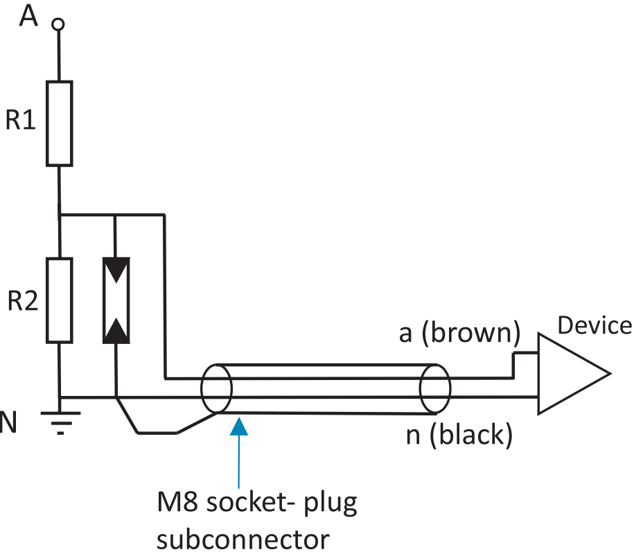
The operation of the voltage sensor is based on the resistive-divider principle, factory-adjusted to the guaranteed accuracy class. It is only necessary to know the resistive value of the input impedance of the measuring device, since the sensor is insensitive to changes in capacitance. Voltage sensors are designed for protection in medium-voltage networks and for measuring systems in accordance with the IEC 61869-11 standard, and are type- and routine-tested.
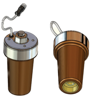
Voltage sensor
NSCxx-xx
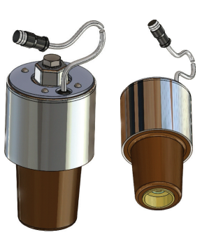
Voltage sensor
NSKxx-xx
Technical data for NSCxx-xx and NSKxx-xx:
| TECHNICAL DATA | VALUES AND CHARACTERISTICS |
|---|---|
| Isolation level | max. 24 / 50 / 125kV |
| Nominal voltage | max. 24/√3 kV |
| Nominal frequency | 50Hz |
| Secondary output | 3,25/√3 V or customer defined |
| Overvoltage factor | 1,9 Un for 8h |
| Accuracy classes | 0,2 / 0,5 / 1 / 3 & 3P / 6P |
| Standard | IEC 61869-11 |
| Input impedances of measurement devices | 200kΩ¹; Capacitance max. 5nF |
| Connection | 2 pole, open wires inclusive screen, cable length in 2m, 10m and 20m² |
| Temperature range | Operating and storage: -40 to +80°C |
| T-Connector for NSCxx-xx | Planned: Südkabel, Nexans, Prysmian, 3M |
| T-Connector for NSKxx-xx | Planned: Südkabel, Nexans, nkt, Raychem, Cellpack, 3M³ |
¹ Accuracy of input impedance of measurement device influences the accuracy of the entire measurement system
Rule of thumb: +/-1% means an additional error of 0.1% in the amplitude
² Cable length could be cut by the customer, if it is necessary
³ A multicompatible sensor for the short cone is used