Current sensors
General information and description
The development of microprocessor technology has led to changes in the requirements for the transformers used for measurement and protection in substations, due to self-powered relays based on microprocessors.
FMT has developed a series of low-power current sensors, compatible with modern microprocessor-controlled relays and secondary equipment with high input impedance. The sensors meet the requirements of the IEC 61869-10 standard.
Installation and mounting
Low-power current sensors are mounted inside the cable compartment of the main unit, designed for installation over the T-connector bushing-type insulator or directly around the power cable itself.
No subsequent field adjustment of the sensor is required, as they are factory-calibrated to deliver an accurate signal in accordance with the applicable IEC standard.
Key advantages of FMT sensors
Low-power current sensors (SSO and SSD series)
Current: 40 - 1000 A | Type: Toroidal / Split core | Output: 225 mV | Standard: IEC 61869-10
Passive devices designed for medium-voltage measurement and protection systems.
Operating principle of current sensors
Current sensors are passive devices whose operation is based on the principle of a toroidal-core transformer or a split-core transformer with an integrated precision shunt. They are designed for medium-voltage measurement and protection systems in accordance with the IEC 61869-10 standard. Current sensors provide a voltage output proportional to the primary current. All current sensors are type- and routine-tested in accordance with the IEC 61869-10 standard.
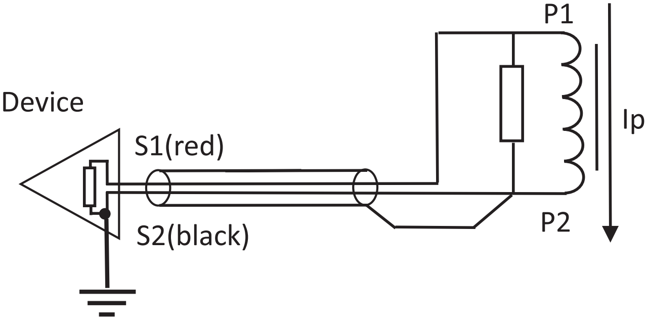
Non-split current sensor
SSOxxx-xx
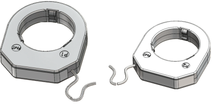
Mounted over the T-connector bushing-type insulator. The internal holders are elastic so they can adapt to any outer diameter of the T-connector.
Split-core current sensor
SSDxxx-xx
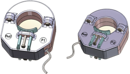
Mounted around the cable. The flexible clamp system enables simple and reliable installation on any cable up to 55mm in diameter.
Technical data for SSOxxx-xx and SSDxxx-xx:
| TECHNICAL DATA | VALUES AND CHARACTERISTICS |
|---|---|
| Isolation level | 0,72 / 3kV / - |
| Nominal primary current | 40-1000A; Extension 200%; or customer defined |
| Secondary output | 225mV acc. IEC; or customer defined |
| Nominal frequency | 50Hz |
| Thermic short current | 25kA 3s |
| Accuracy classes SSOxxx-xx | 0,2S / 0,2 / 0,5S / 0,5 / 1 / 3 & max. 5P20 |
| Accuracy classes SSDxxx-xx | 0,5S / 0,5 / 1 / 3 & max. 5P20 |
| Standard | IEC60044-8 / IEC61869-11 (future) |
| Input impedances of measurement devices | 20kΩ¹; capacitance not relevant |
| Connection | 2pole, open wires inclusive screen |
| Temperature range | Operating and storage: -40 to +80°C |
¹ The input impedance of the measurement device influences the accuracy of the entire system. The higher the impedance - the better. With 20kΩ an additional error of 0.02% in amplitude error will be generated.