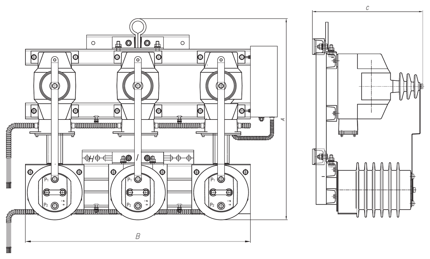
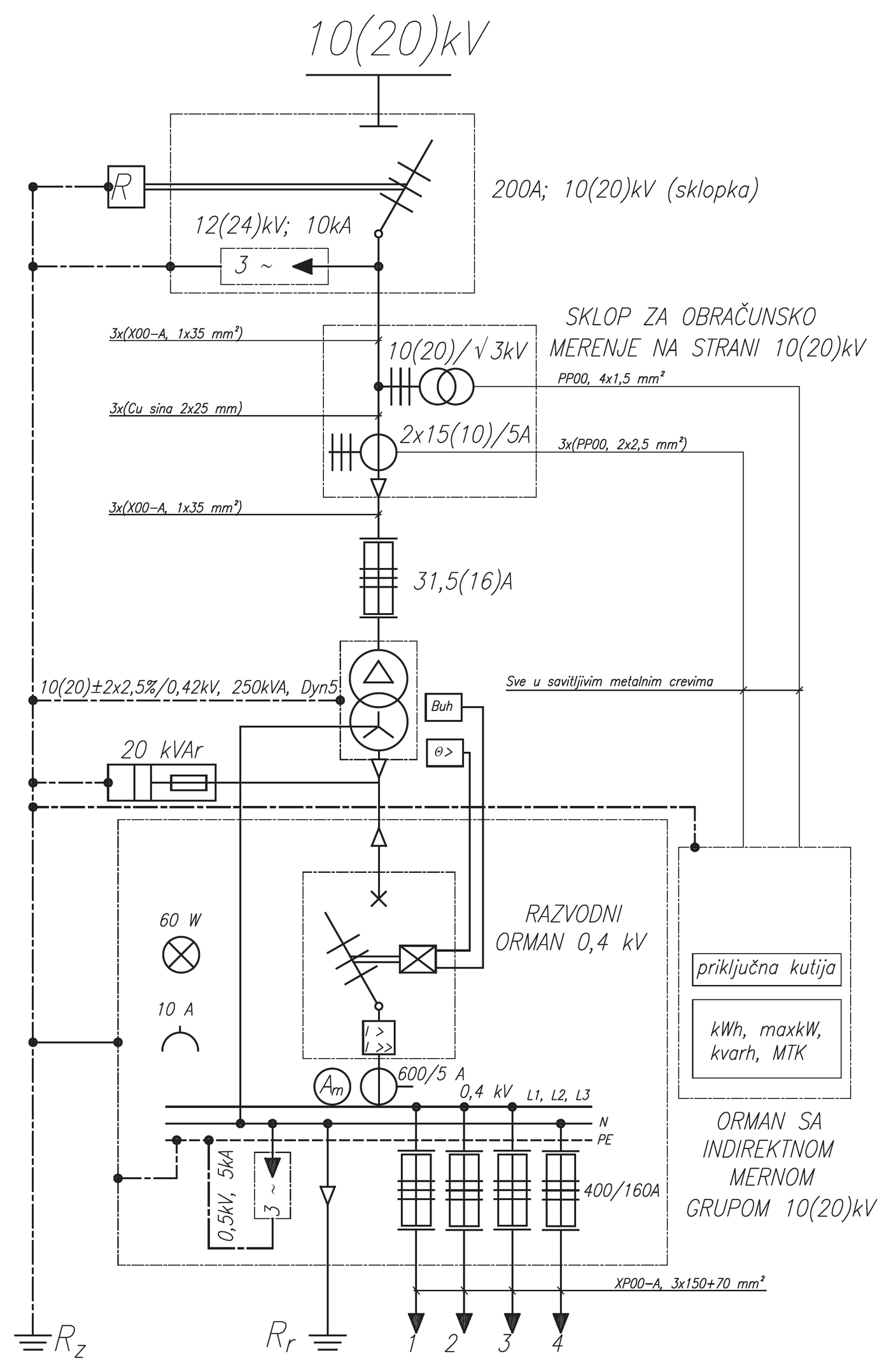
Billing metering assemblies for pole-mounted substations
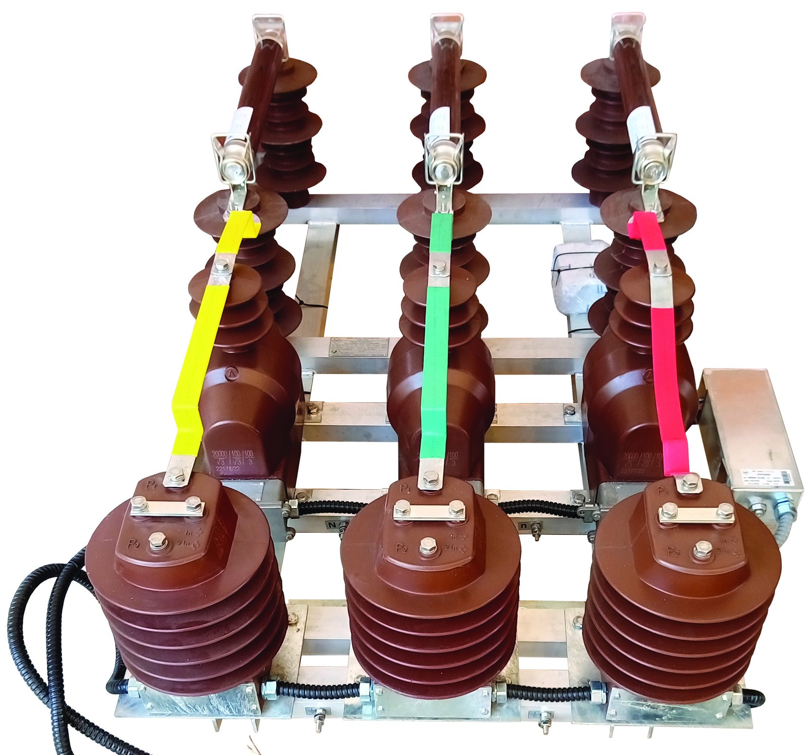
Under the EPS tariff system, prices are set for the active and reactive energy taken and for the maximum active power, and they differ according to the voltage level at which billing metering is performed.
For connection at higher voltage levels, the consumer's contribution to the cost of building power facilities (per 1 kW) is higher, but the prices for the active and reactive energy taken and for the maximum active power are lower.
The consumer has the right to choose the voltage level at which they want to be billed, according to their needs.
In the long run, it is more cost-effective for the consumer to pay at the higher voltage level, provided that maintaining the power facility is not a burden.
From the electricity supplier's point of view, supply at a higher voltage level is more favourable for at least 2 reasons:
- losses in the power transformer and in transmission to the metering point are included in the bill;
- there is no obligation to maintain the installation, since by law the supplier's responsibility extends up to the metering point (including the metering point).
Investors who want the STS to be their property could not, formally, achieve this without such a solution, because of the provision of the Energy Law that the boundary of responsibility is the metering point.
Until 15 years ago, billing metering at the 10 kV, 20 kV and 35 kV level was only possible in indoor transformer substations, where the instrument transformers were installed in metal-clad metering (and coupling-metering) cubicles as part of a 10 kV, 20 kV or 35 kV switchgear.
Since the proposer of the solution – the Factory of Measuring Transformers Zaječar – has in its product range all the elements needed for outdoor billing metering (for outdoor mounting), the idea arose for such a project, with the aim of offering interested electricity distribution companies and investors a solution that suits both sides.
The solution offered by this project is the SMST BILLING METERING ASSEMBLY (hereinafter SMST), for outdoor mounting, which can be installed primarily on pole-mounted transformer substations, but also at branch points from a 10 kV, 20 kV or 35 kV overhead line (cable or aerial bundled cable 10 kV, 20 kV or 35 kV) for supplying consumers at the 10 kV, 20 kV and 35 kV level.
Three variants of the SMST assembly
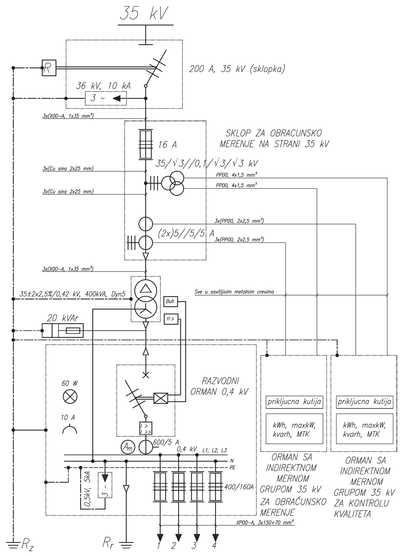
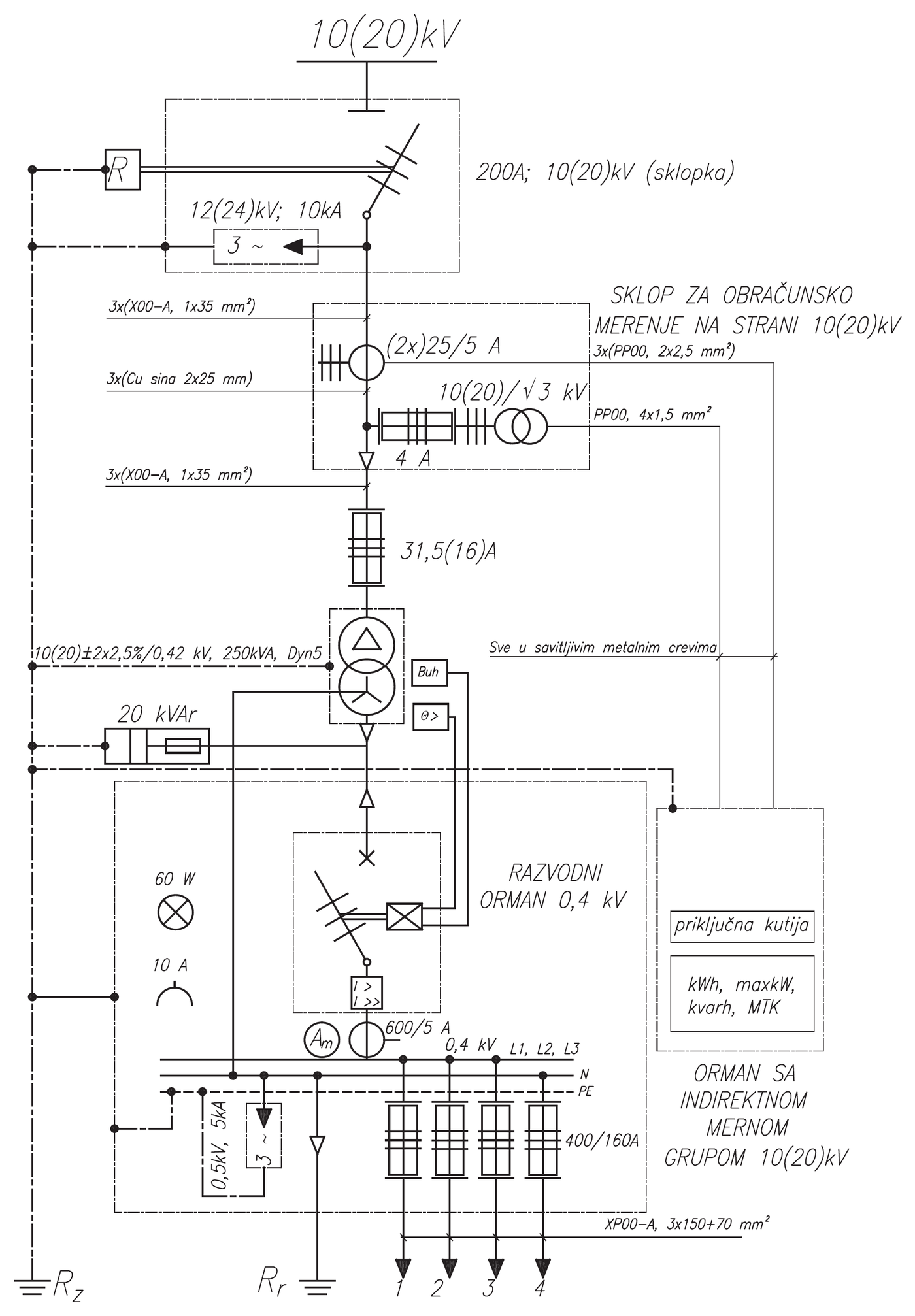
This project provides three variants of the assembly for three-system indirect metering on pole-mounted substations:
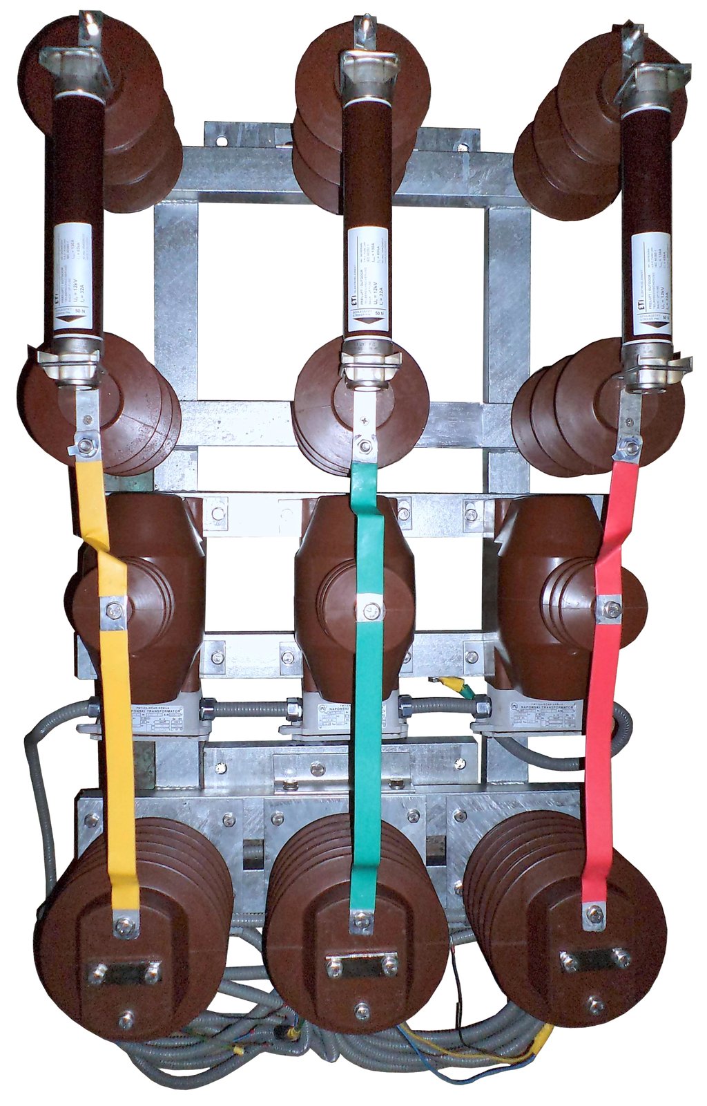
3 instrument current and 3 instrument voltage transformers with VVC fuses that protect the supply lines and the power transformer against short circuits. Often used when the technical conditions require the assembly to be installed on the pole before the pole carrying the pole-mounted substation.
Model information3 instrument current and 3 instrument voltage transformers with VVC fuses that protect the instrument voltage transformers and other elements against short circuits. This variant is most often made at the request of customers who want to meet the requirement of protecting voltage transformers against ferroresonance when the assembly is used in isolated networks.
Model information3 instrument current and 3 instrument voltage transformers with the appropriate connections (without VVC fuses).
Model informationElements of the three-system billing metering assembly
Click an element to show its description and technical data.
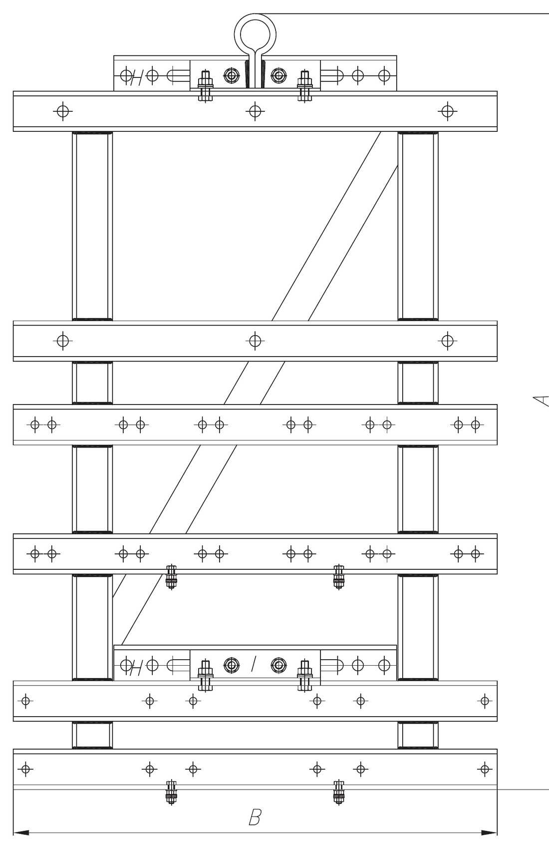
The support structure is metal, made of welded aluminium profiles 60x40 mm. The steel parts are protected against corrosion by hot-dip galvanizing.
It is intended for mounting on the round shaft of an overhead-line pole by means of 2 general-purpose brackets made of standard steel channel NP U6.5, with stirrups adapted to the mounting height.
The support structure is attached to the general-purpose brackets by means of 2 ties made of standard angle profile NP L 5.
The fuse holders used are mounted on C4-125 apparatus insulators, certified for an operating voltage of 20 kV, or C4-170d for an operating voltage of 35 kV.
The forks (clamps) for the HV fuses are made of hard copper, protected against corrosion by electrolytic tin plating. The mechanical locks that prevent the HV fuse-links from falling out are made of galvanized steel.
10/√3 kV/kV, 20/√3 or 35/√3 kV/kV; They are connected between phase and earth.
The magnetic cores of these transformers are of the stacked type and the windings are made of copper in layers. This ensures a rational distribution of radial and axial stresses, as well as good withstand to power-frequency and impulse overvoltages. Since the transformers are fully encapsulated, the result is a one-piece body with a smooth surface whose homogeneity ensures high dielectric strength and mechanical durability. They cannot catch fire and the insulation cannot leak. They are smaller, as they have special electromagnetic field absorbers. They can be installed anywhere and in any position. No maintenance is required, they do not pollute the environment and produce no noise. They have a longer service life under operating conditions. They are smaller, cost less, and installation is easier and cheaper.
| Type | JNT SM-12 | JNTm2 SM-24 | JNT SM36-6R |
|---|---|---|---|
| Maximum equipment voltage (kV) | 12 | 24 | 38 (36) |
| Rated primary voltage (kV) | 10/√3 | 20/√3 | 35/√3 |
| Rated secondary voltage (V) | 100/√3 | 100/√3 | 100/√3 |
| Test voltage 50 Hz, 1 min (kV) | 28 | 50 | 70 |
| Lightning impulse test voltage 1.2/50 µs (kV) | 75 | 125 | 170 |
| Rated frequency (Hz) | 50/60 | ||
| Rated accuracy class | 0,5 | 0,5 | 0,5 (0,2) |
| Rated burden (VA) | 30 | 30 | 30 (15) |
| Creepage distance (mm) | 500 | 535 | 920 |
| Weight (kg) | 26 | 28 | 43 |
| Insulation thermal class | E/B | ||
| Type of main insulation | Cycloaliphatic resin | ||
| Operating temperature range | -50 °C to +50 °C | ||
| Applicable standards | SRPS EN 61869-1, SRPS EN 61869-3 | ||
| Technical data | ATMS-2411 | ATM-3820h (ATM-3821h) |
|---|---|---|
| Rated voltage (kV) | 20 | 35 |
| Highest voltage for equipment (kV) | 24 | 38 (36) |
| Test voltage 50 Hz, 1 min (kV) | 50 | 70 |
| Lightning impulse test voltage 1.2/50 µs (kV) | 125 | 170 |
| Rated frequency (Hz) | 50/60 | |
| Rated primary current (A) | 2x5 to 2x600 | |
| Rated secondary current (A) | 5 (or 1) | |
| Rated thermal current, 1 s | Ith = (100-200) In | |
| Rated dynamic current | Idyn = 2,5 Ith | |
| Continuous thermal current | Icth = 1,2 In | |
| Security factor | FS5 | |
| Rated burden (VA) | 10 | 15/15 |
| Rated accuracy class | 0,5 | 0,2; 0,5 (0,2S; 0,5S) |
| Number of cores | 1 | 2 |
| Creepage distance (mm) | 570 | 1296 |
| Weight (kg) | ~15 | ~54 |
| Insulation thermal class | E/B | |
| Type of main insulation | Cycloaliphatic resin | |
| Operating temperature range | -50 °C to +50 °C | |
| Applicable standards | SRPS EN 61869-1, SRPS EN 61869-2 | |
A resistor (25 Ω, 400 W for 10 and 20 kV, or 16,6 Ω, 600 W for 35 kV) is located in the open delta of the residual windings to protect the voltage transformers against ferroresonance when the assembly is used in isolated networks. It is connected in series in the tertiary circuit of the 3 single-pole instrument voltage transformers in networks with an isolated neutral.
Ferroresonance protection resistors in our rangeIn a separate cabinet on the pole-mounted substation itself. Not part of the SMST assembly.
Metering of consumed electrical energy and peak demand (the maximum 15-minute power reached in the billing period) is provided by a three-system metering unit for indirect metering on the 10 kV, 20 kV or 35 kV side, housed in a separate cabinet mounted on the pole shaft.
A metering unit with a multifunctional digital meter for three-system metering is recommended.
The meter would perform:
- metering of consumed active energy in 2 tariffs, class 1;
- metering of consumed reactive energy in 2 tariffs, class 3;
- metering of the maximum 15-minute active power reached, in 2 tariffs, class 1;
- reception of ripple-control (MTK) telegrams;
- storage of peak demand values for the last 12 reading cycles.
The meter must be approved for use by the Federal Institute of Measures and Precious Metals and accepted for use in the distribution area.
The factory does not supply the metering unit and cabinet as part of the SMST, but customers who want them can order them separately.
For the 35 kV voltage level, 2 metering units are provided – one for billing metering and the other for quality control – and both should be bidirectional so that the assembly can be used at solar power plants. On request we can also make an assembly for two-system billing metering, which is covered in a separate brochure.
Mounting the assembly on the pole
The SMST can be installed on the same side of the pole as the power transformer or on the opposite side. Click a drawing to view it full screen.
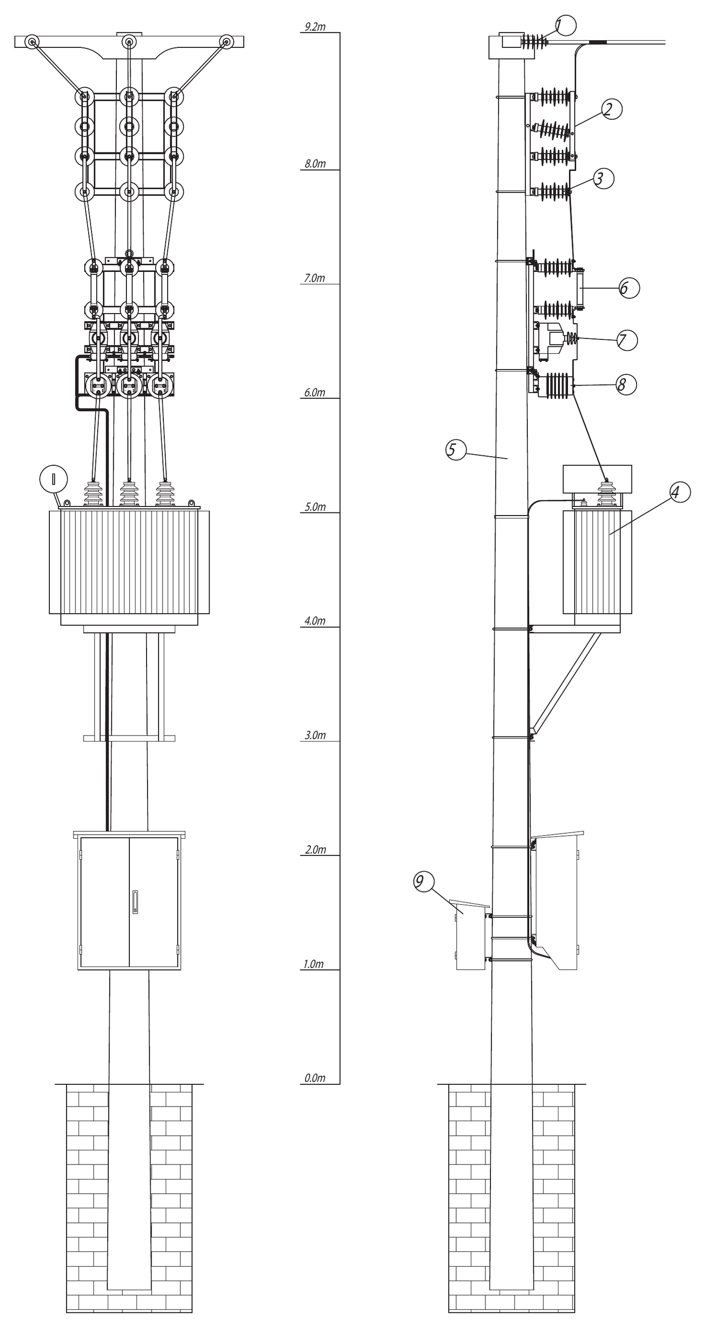
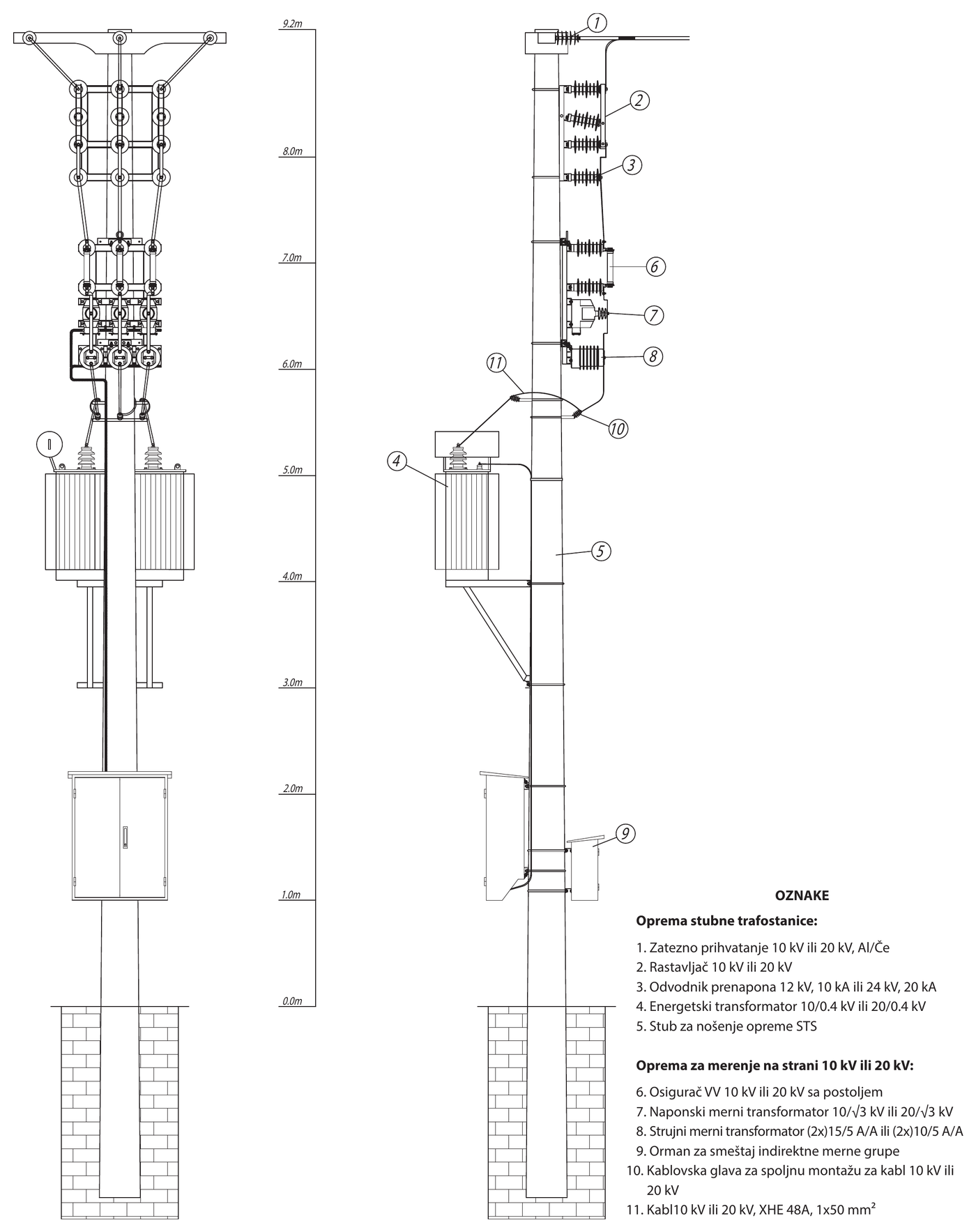
Correct selection of instrument transformers for the assembly
Three-system metering requires 3 current and 3 voltage instrument transformers for outdoor mounting, rated for the voltage level of the network where the metering takes place. It is important that the transformation ratio and burden of the instrument transformers are determined as accurately as possible so that the metering is as precise as possible.
Instrument voltage transformers
The primary voltage of the instrument voltage transformers is the phase voltage of the network (for three-pole assemblies 10/√3, 20/√3 or 35/√3 kV, and for two-pole assemblies 10, 20 or 35 kV).
The secondary voltage of the instrument voltage transformers is 100/√3 V or 110/√3 V.
The rated burden of the secondary and/or tertiary winding should cover the consumption of the connected measuring or protection devices supplied in that circuit plus the Joule power losses in the leads themselves, given in the table.
Instrument current transformers
The primary current of the instrument current transformers is the line current calculated from the rating of the power transformer in front of which the assembly is installed, rounded up to the nearest higher standard value.
Since the power transformer itself is not always loaded with its rated power, the rated primary current of the current transformers should be determined as realistically as possible.
The rated burden of each secondary winding of the instrument current transformer should cover the consumption of all measuring or protection devices connected to the secondary terminals of that winding plus the Joule power losses in the leads themselves, according to the table.
Joule power losses in the connecting leads
They are taken into account in addition to the consumption of the measuring or protection devices themselves.
| Load | Power consumption per system (W/m) |
|---|---|
| Cu conductor 1 m, 2.5 mm² at 5 A | 0,18 |
| Cu conductor 1 m, 4 mm² at 5 A | 0,11 |
| Cu conductor 1 m, 1.5 mm² at 1 A | 0,012 |
| Cu conductor 1 m, 2.5 mm² at 1 A | 0,007 |
| Cu conductor 1 m, 4 mm² at 1 A | 0,0044 |
Standard burdens
Write to us – based on the power transformer rating and the network voltage level, our experts will propose the optimal transformation ratio and burden of the instrument transformers for your assembly.
Equipment earthing and protection against dangerous touch voltage
Equipment earthing
All equipment provided is insulated. The secondary circuits of the instrument current transformers are earthed directly at the terminals of the instrument current transformers and connected to the metal support structure. The same applies to the secondary circuits (windings) of the instrument voltage transformers.
The support structure is connected to the earthing busbar of the pole by means of an ELDS kit, which is not part of the SMST but can be ordered separately. For this purpose, a 13 mm hole is provided in the upper crossbar of the structure. Since the support structure has a profile cross-section greater than 100 mm², it is used as part of the earthing conductor for connecting the earthing of the equipment it carries.
Protection against dangerous touch voltage
The height from the ground to unprotected live parts of the equipment is more than 5 m, and all cables up to a height of at least 2 m have mechanical protection, earthed to the STS earthing conductor. All supply lines provided are of suitable construction and have the necessary insulation or are laid in protective conduits, and their correct entry into cabinets and protective housings of electrical equipment is also provided for.
SMST assembly models
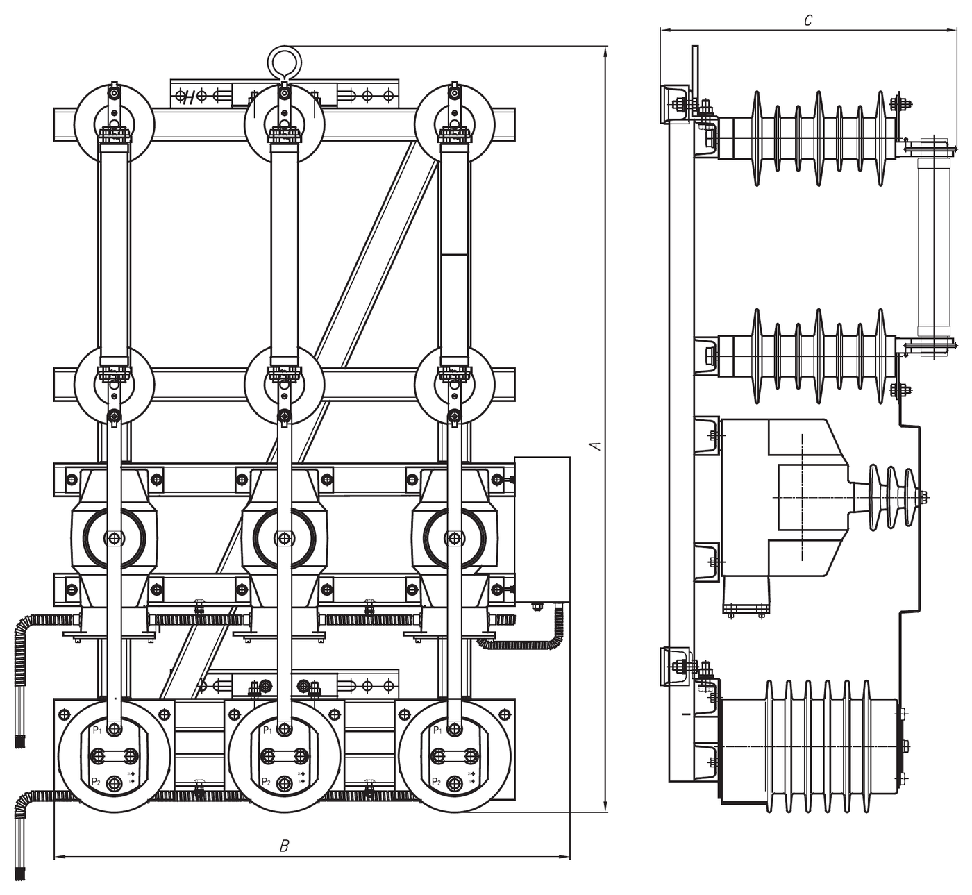
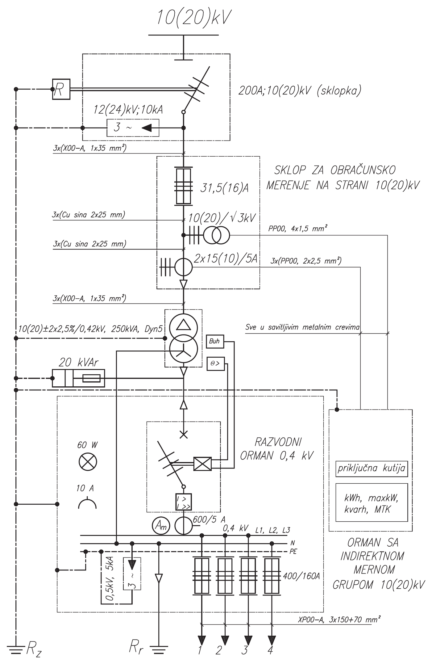
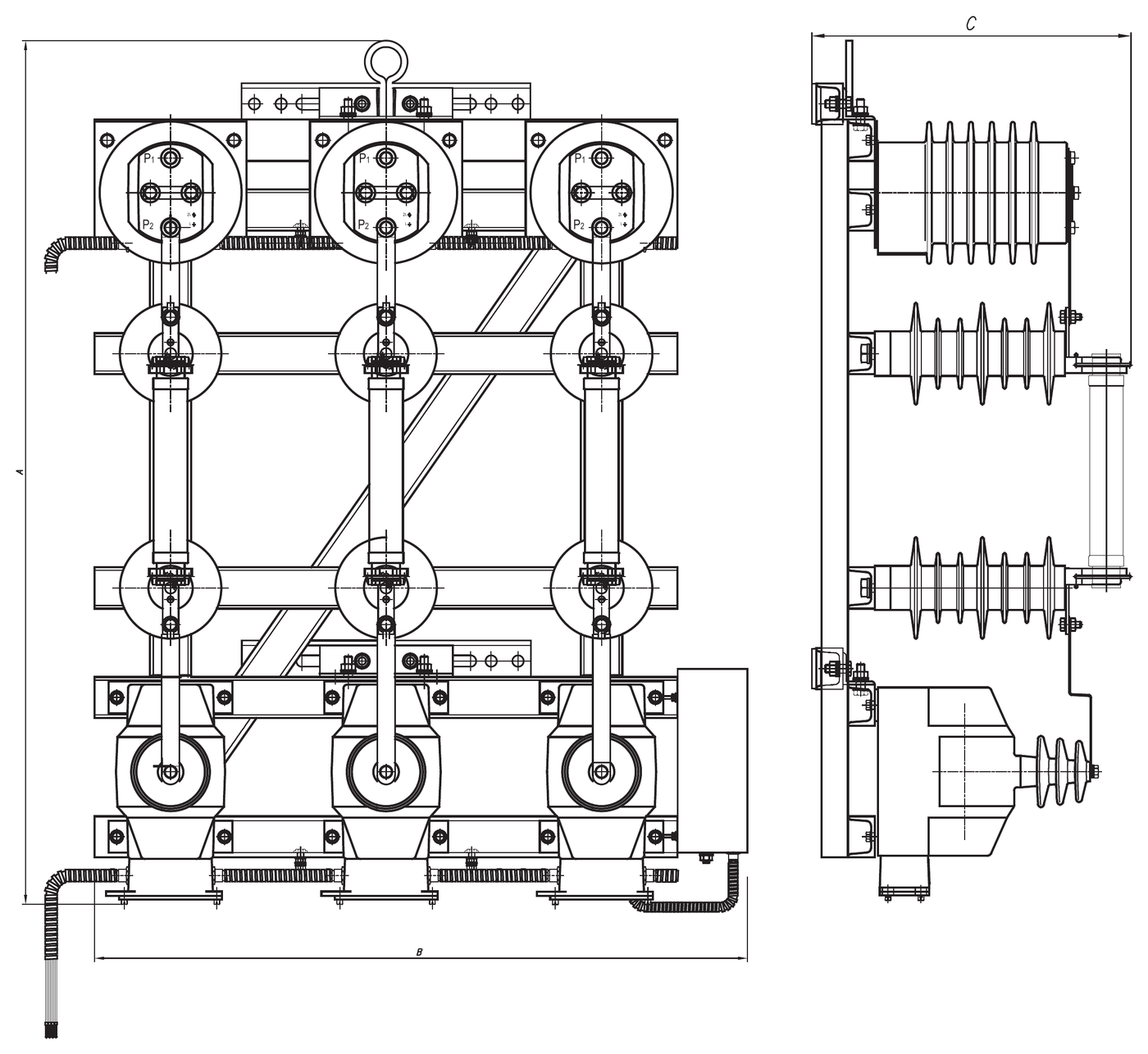
Click a photo for an enlarged view (hover over it for the assembly sketch), and “More about the model” for the description, dimensions, weights and single-line diagrams.
Three-system billing metering assembly
SMST-V1
Maximum voltage – 12 kV, 24 kV, 36 kV
3 instrument current and 3 instrument voltage transformers with VVC fuses that protect the supply lines and the power transformer against short circuits.
Three-system billing metering assembly
SMST-V2
Maximum voltage – 12 kV, 24 kV, 36 kV
3 instrument current and 3 instrument voltage transformers with VVC fuses that protect the instrument voltage transformers and other elements against short circuits.
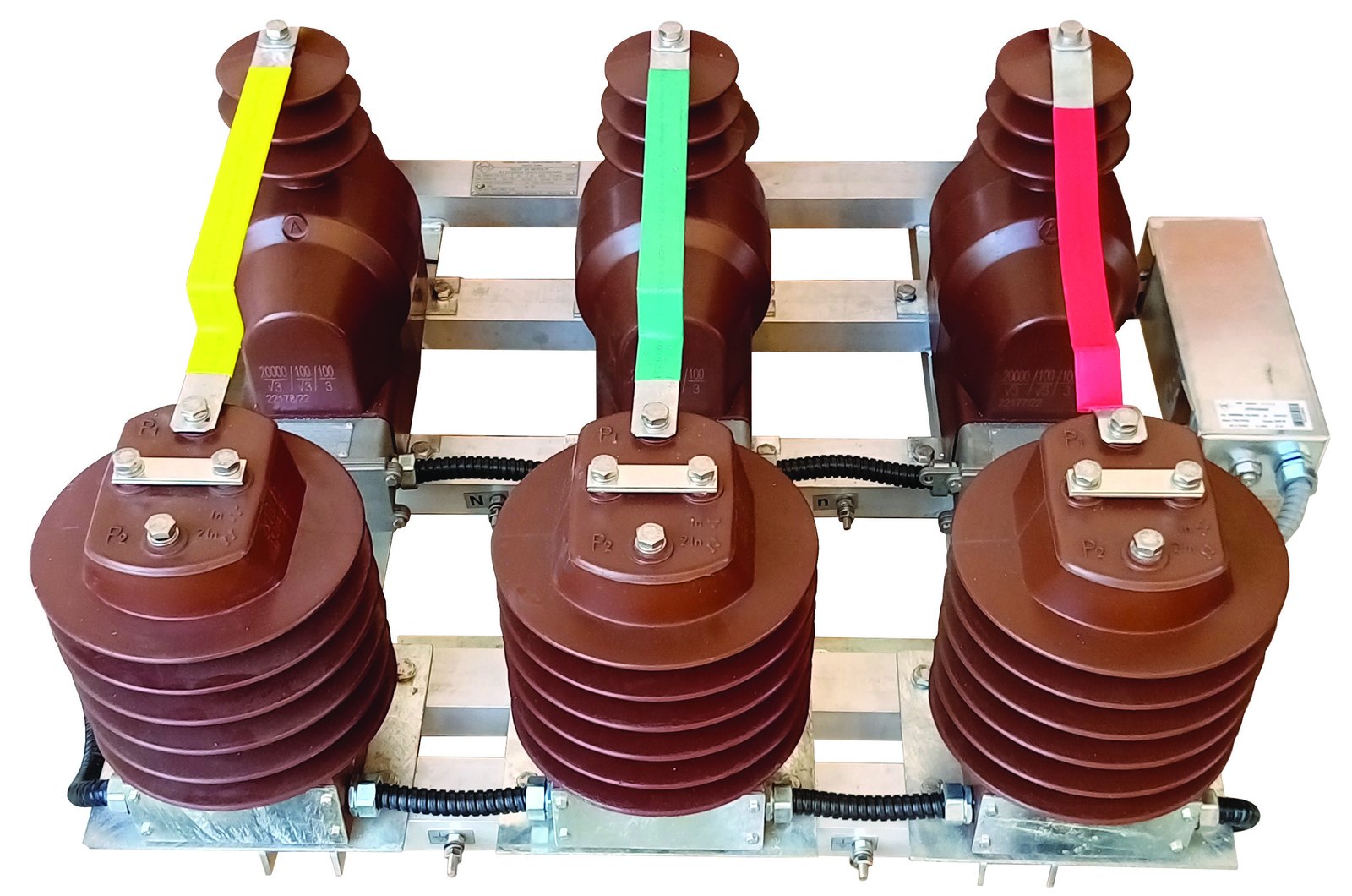
Three-system billing metering assembly
SMST-V3
Maximum voltage – 12 kV, 24 kV, 36 kV
3 instrument current and 3 instrument voltage transformers with the appropriate connections (without VVC fuses).