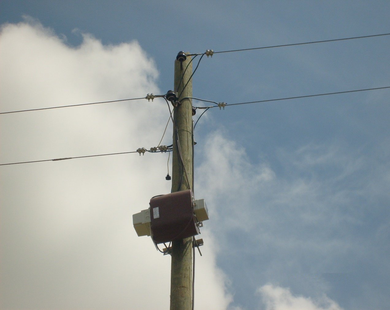
Self-manageable voltage regulators
Application
The self-manageable voltage regulator is intended for managing voltage conditions in low-voltage networks. This is achieved by balancing the load along the line where it is installed, as well as by reducing the return current in the neutral conductor for consumers connected downstream of the VROT-* device. It also improves the operating conditions and selectivity of protection, and protects consumers against overvoltage in the event of short circuits between the phase and neutral conductors.
It is highly suitable for use in industrial facilities, large buildings and shopping centres as a distributed power supply system for remote consumers.
It features a high degree of maximum power transmission along the low-voltage line.
Description
All live parts of the device are covered.
The basic elements are: the fuse box, a special galvanically isolated dry-type power transformer and the control box.
Fuse box
It is equipped with an automatic circuit breaker of high breaking capacity. The cover is transparent, so the status of the switching and protective element can be checked visually.
Dry-type power transformer
This is a special type of controllable transformer whose operation is based on the principle of controlling the variable structure of a galvanically separated circuit, and it does not belong to the group of autotransformers. The basic insulation is made of cycloaliphatic epoxy resins intended for outdoor installation, and the dimensions are optimised with regard to power rating and place of installation. Special attention has been paid to the design and to the mechanical and electrical characteristics in terms of thermodynamic and dielectric stresses and losses (iron and copper losses), which makes it highly efficient, reliable and attractive.
Control box
It is made of top-quality PVC materials with IP 54 protection, and is equipped with electronics that are galvanically separated from the low-voltage network and that control the transformer.
Through a special actuator, the electronics command the transformer to enter regulation. The electronic assembly also has a self-test function.
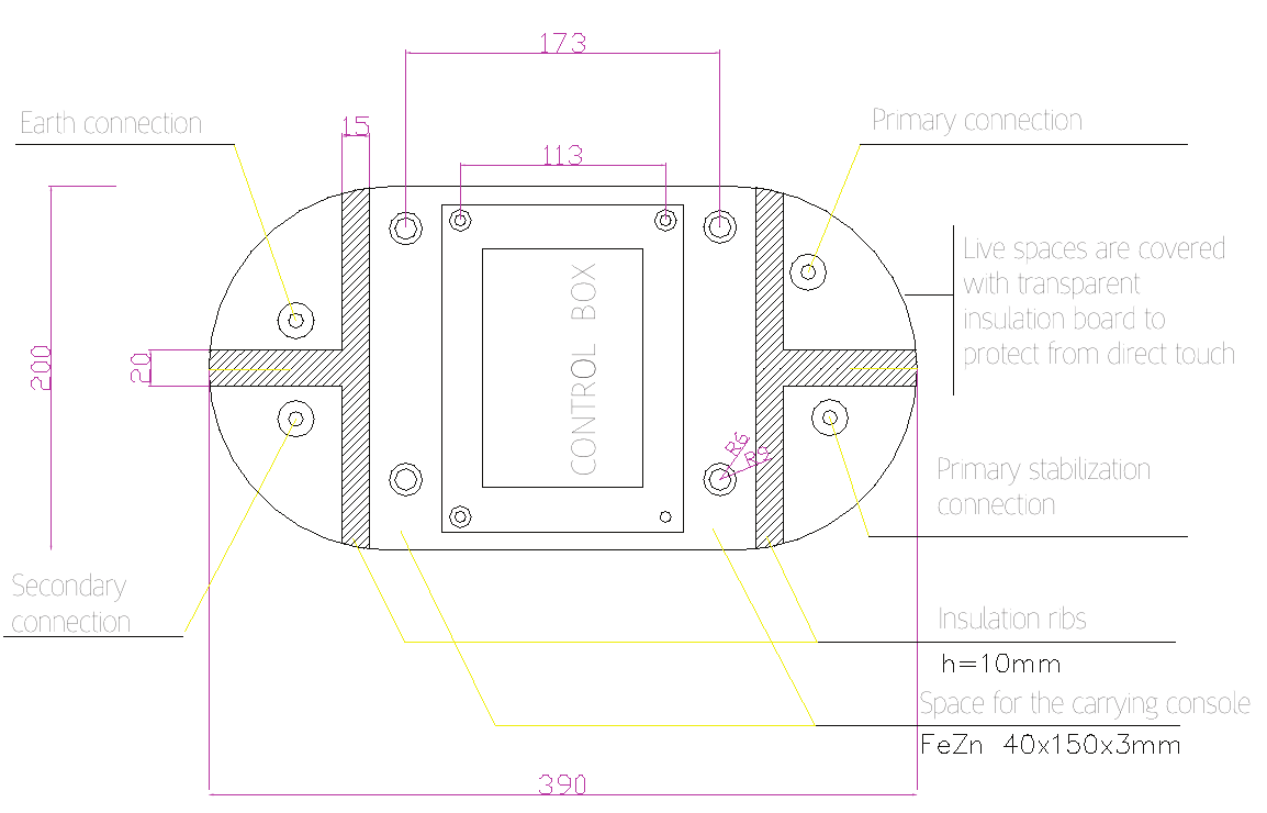
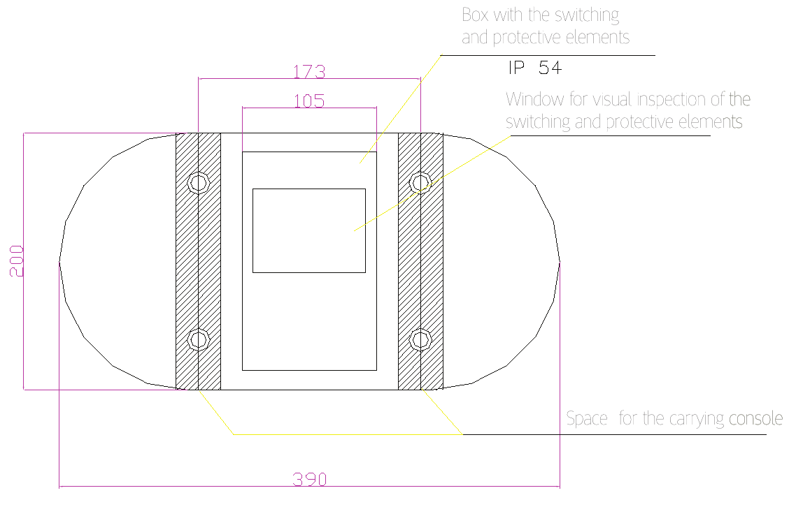
Hover over the image to zoom in (click to view full size)
Operating principle
The electronics monitor the parameters of the low-voltage line at the point of installation and perform control according to the stored program. By installing the device at the designed point on the low-voltage feeder, parameters identical to those on the busbars of the associated 10(20)/0.4 kV substation are obtained, thus achieving the method of mirroring the 10(20)/0.4 kV substation to the point where the device is installed.
Method and place of installation
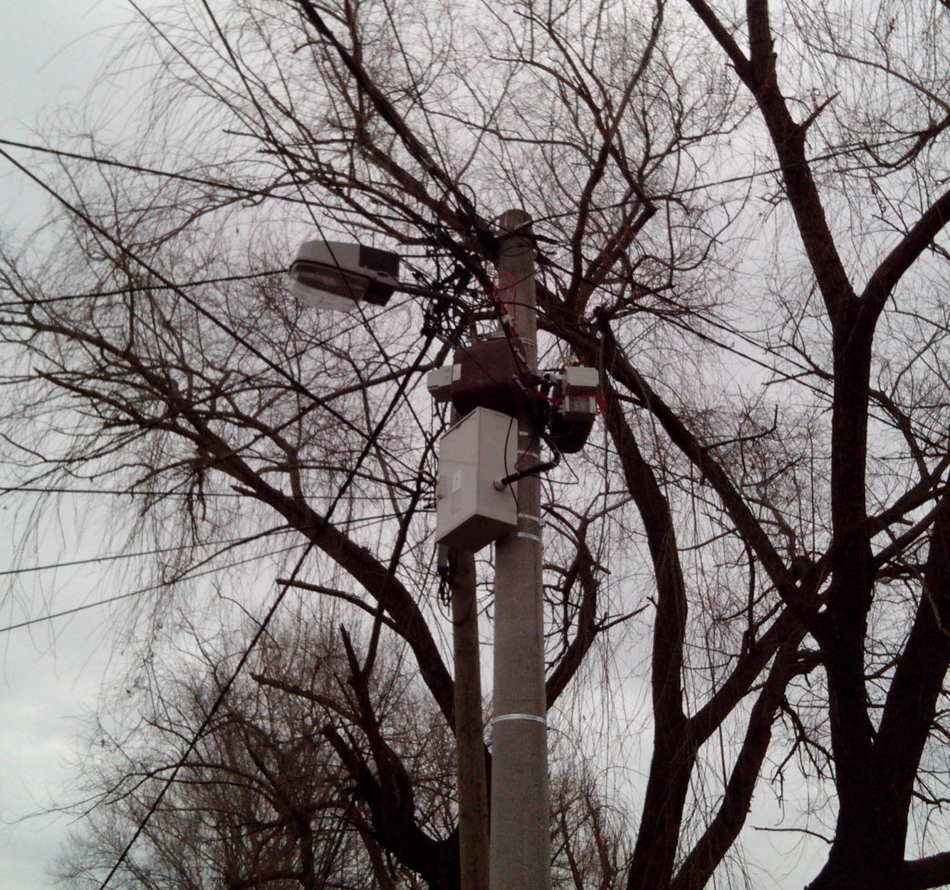
The self-manageable voltage regulator is mounted on a specially designed stainless metal bracket. It is installed 1 m below the lowest conductor of the LV network. Connection to the low-voltage network is made by connecting the primary conductors to the line voltage of the network, while the secondary is connected to the phase and neutral conductors. Combined earthing must be provided at the place of installation. One power transformer is used per phase, and each has its own fuse box and control box. The self-manageable voltage regulator regulates the voltage separately for each phase.
Self-manageable voltage regulators
VROT-10 and VROT-18
| Transformer type | VROT-10 | VROT-18 |
|---|---|---|
| Rated power [kVA] | 10 | 18 |
| Rated network voltage [V] | 400/231 | |
| Output voltage [V] | 230 ± 10% | |
| Insulation level [kV] | 1 | |
| Test voltage 50 Hz, 1 min [kV] | 3 | |
| Impulse voltage 1.2/50 μs [kV] | 6 | |
| Rated output current [A] | 44 | 80 |
| Transformer losses Pcun [W] / Pfe [W] | 310/50 | 500/80 |
| Transformer power factor cos φ | 0.95 | |
| Degree of mechanical protection | IP 54 | |
| Temperature range | -35 °C to 80 °C | |
| Mounting | in all positions on the pole | |
Benefits provided by this system
- simple and quick installation;
- low investment when reconstructing the network;
- significantly higher system efficiency in energy transmission along the LV line;
- reduced energy losses in transmission to consumers;
- possibility of transmitting significantly higher power over longer distances while maintaining continuous voltage conditions along the low-voltage line within the limits defined by IEC 60038/EN 50160;
- the influence of higher harmonics is eliminated thanks to galvanic separation;
- the load on the neutral conductor in the substation is eliminated under large asymmetries, since I0 = 0 at the point of installation;
- improved protection conditions of the TN-C-S system;
- protection of consumers against overvoltage in the event of a short circuit between the phase and neutral conductors or a break of the neutral conductor;
- load balancing across the phase conductors;
- selectivity and sensitivity of protection along the low-voltage line are achieved;
- in combination with a self-supporting cable bundle, no maintenance of that substation feeder is required, especially if the power line passes through areas with tall vegetation;
- highly suitable as a replacement for 10/0.4 kV substations of up to 50 kVA when supplying small consumer areas;
- when used as a replacement for 10/0.4 kV substations of up to 50 kVA, the number of outages of the main 10(20) kV trunk lines is reduced, as faults on high-voltage lines that pass through areas with tall vegetation and supply low-power 10/0.4 kV substations are avoided;
- the VROT-18 type is highly suitable for a ring network concept with 10/0.4 kV, 250 kVA substations with 5 outgoing feeders of 50 kVA each;
- highly suitable for use in industrial facilities, large buildings and shopping centres as a distributed power supply system for remote consumers.
Effects of installing the regulating transformer in the LV network
With VROT 18 in the low-voltage network
| Rated voltage at the 10(20)/0.4 kV, 250 kVA substation Level 1 | Conductor used in the low-voltage network Level 1 to Level 2 | LV line length [m] | Rated power / Line voltage / Phase voltage at the end of the line Level 2 | |
|---|---|---|---|---|
| Symmetrical 3 phases | Asymmetrical 1 phase | |||
| 231/400 V | AlFe 3x 25/4 mm or X00-A-3x25 mm² | 800 | 16kW/400/230V | 7.8kW/230V |
| 450 | 30kW/400/230V | 13.8kW/230V | ||
| 250 | 50kW/400/230V | 18kW/230V | ||
| AlFe 3x 35/6 mm or X00-A-3x35 mm² | 1100 | 16kW/400/230V | 7.8kW/230V | |
| 500 | 30kW/400/230V | 13.8kW/230V | ||
| 300 | 50kW/400/230V | 18kW/230V | ||
| AlFe 3x 50/8 mm or X00-A-3x50 mm² | 1500 | 16kW/400/230V | 7.8kW/230V | |
| 800 | 30kW/400/230V | 13.8kW/230V | ||
| 500 | 50kW/400/230V | 18kW/230V | ||
| X00-A-3x70 mm² | 2000 | 16kW/400/230V | 7.8kW/230V | |
| 1000 | 30kW/400/230V | 13.8kW/230V | ||
| 600 | 50kW/400/230V | 18kW/230V | ||
X00-A is a self-supporting cable bundle.
Without VROT 18 installed in the low-voltage network
| Rated voltage at the 10(20)/0.4 kV, X kVA substation Level 1 | Conductor used in the low-voltage network Level 1 to Level 2 | LV line length [m] | Rated power / Line voltage / Phase voltage at the end of the line Level 2 | |
|---|---|---|---|---|
| Symmetrical load 3 phases | Asymmetrical load 1 phase | |||
| 231/400 V | AlFe 4x 25/4 mm or X00-A-4x25 mm² | 400 | 16kW/376/217V | 5.00kW/207V |
| 225 | 30kW/376/217V | 8.66kW/207V | ||
| 125 | 50kW/376/217V | 15.4kW/207V | ||
| AlFe 4x 35/6 mm or X00-A-4x35 mm² | 550 | 16kW/377/218V | 5.00kW/207V | |
| 320 | 30kW/377/218V | 8.66kW/207V | ||
| 180 | 50kW/377/218V | 15.4kW/207V | ||
| AlFe 4x 50/8 mm or X00-A-4x50 mm² | 770 | 16kW/377/218V | 5.00kW/207V | |
| 450 | 30kW/377/218V | 8.66kW/207V | ||
| 260 | 50kW/377/218V | 15.4kW/207V | ||
| X00-A-3x70+71.5 mm² | 1000 | 16kW/377/218V | 5.00kW/207V | |
| 600 | 30kW/377/218V | 8.66kW/207V | ||
| 340 | 50kW/377/218V | 15.4kW/207V | ||
For transmitting higher power from the beginning to the end of the line, as well as for distances greater than those shown in TABLE 1.0, larger conductor cross-sections must be used.
Effect of VROT installation – network voltage recording
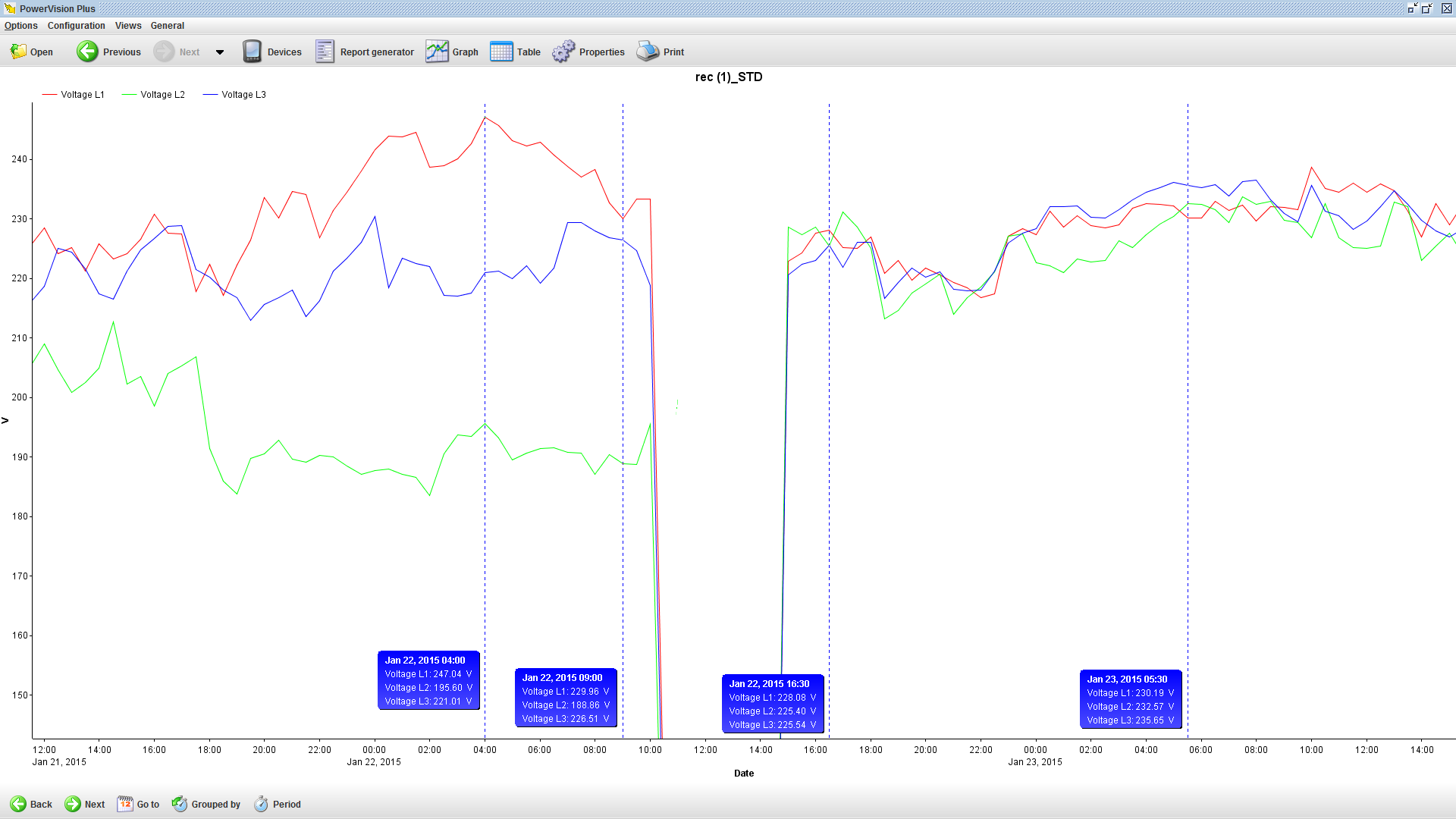
Click on the graph to view it full size, then hover over it to zoom in on details
Effects of installing a single-phase VROT 18 in a single-phase low-voltage network
| Method | With VROT 18 | Without VROT 18 | |||
|---|---|---|---|---|---|
| Level 2 | Phases at the consumer | R | N | R | N |
| Power at the consumer | 12.70 kW | 7.61 kW | |||
| Current through the consumer | 55.5 A | 55.5 A | 42.52 A | 42.52 A | |
| Voltage at the consumer | 230.00 V | 179.00 V | |||
| Consumer is supplied via | VROT 18 | Al/Fe -2 x 50/8 mm² | |||
| Connection towards the substation | R | S | R | N | |
| Low-voltage power line 1000 m | Conductor used | Al/Fe -2 x 50/8 mm² | Al/Fe -2 x 50/8 mm² | ||
| Current flowing through the line towards the substation | 36.60 A | 36.60 A | 42.52 A | 42.52 A | |
| Losses on the low-voltage power line [kW] | 0.80 | 0.80 | 1.08 | 1.08 | |
| SS 10(20)/0.4 kV Level 1 | Rated voltage at the substation | 230 V | |||
The problem of continuously maintaining the voltage within the limits defined by IEC 60038/EN 50160 along a low-voltage power line, from the associated 10/0.4 kV substation to the last consumer, in operating modes ranging from asymmetrical to symmetrical load, is not easy to solve. Changing the conductor cross-section or increasing the voltage at the associated 10/0.4 kV substation has proven to be ineffective. This can be seen from the comparative analysis of the results without and with VROT-* installed according to Tables 1.0 and 1.1, as well as for the case of supplying a single-phase consumer area shown in Table 2.
If the development concept of the medium- and low-voltage network is based on ring supply via 10/0.4 kV, 250 kVA substations with 5 feeders, then at least one feeder could always be used to supply remote consumers, using a combination of a suitable conductor cross-section and the VROT-X device, depending on the required power of the consumer area, in accordance with Table 1.0.
By applying the above system to supply a small consumer area of up to 50 kVA, compared with conventional solutions (power transmission over a 10(20) kV power line and a 10(20)/0.4 kV, 50 kVA substation), we achieve:
- lower maintenance costs, especially if the power line passes through areas with tall vegetation where the route (clearing) must be maintained, or when a high-voltage cable bundle is used;
- faster, cheaper and easier network maintenance when a low-voltage cable bundle with a VROT-X device is used as the primary supply line for a small consumer area instead of a high-voltage cable bundle;
- fewer outages of the 10(20) kV trunk power line when bare Al/Fe conductors are used as primary conductors and the line passes through areas with tall vegetation.
Application of VROT-18 in the network
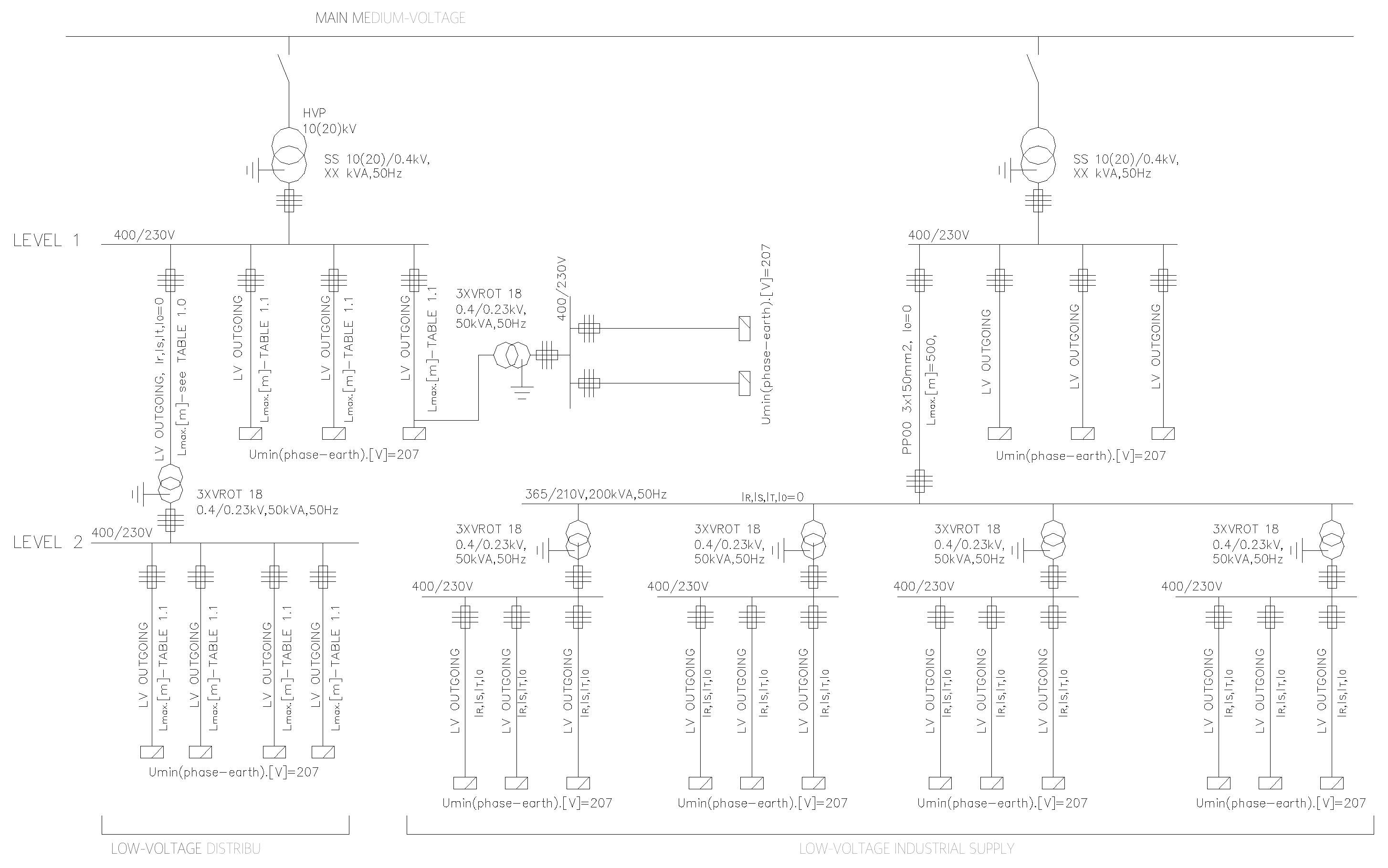
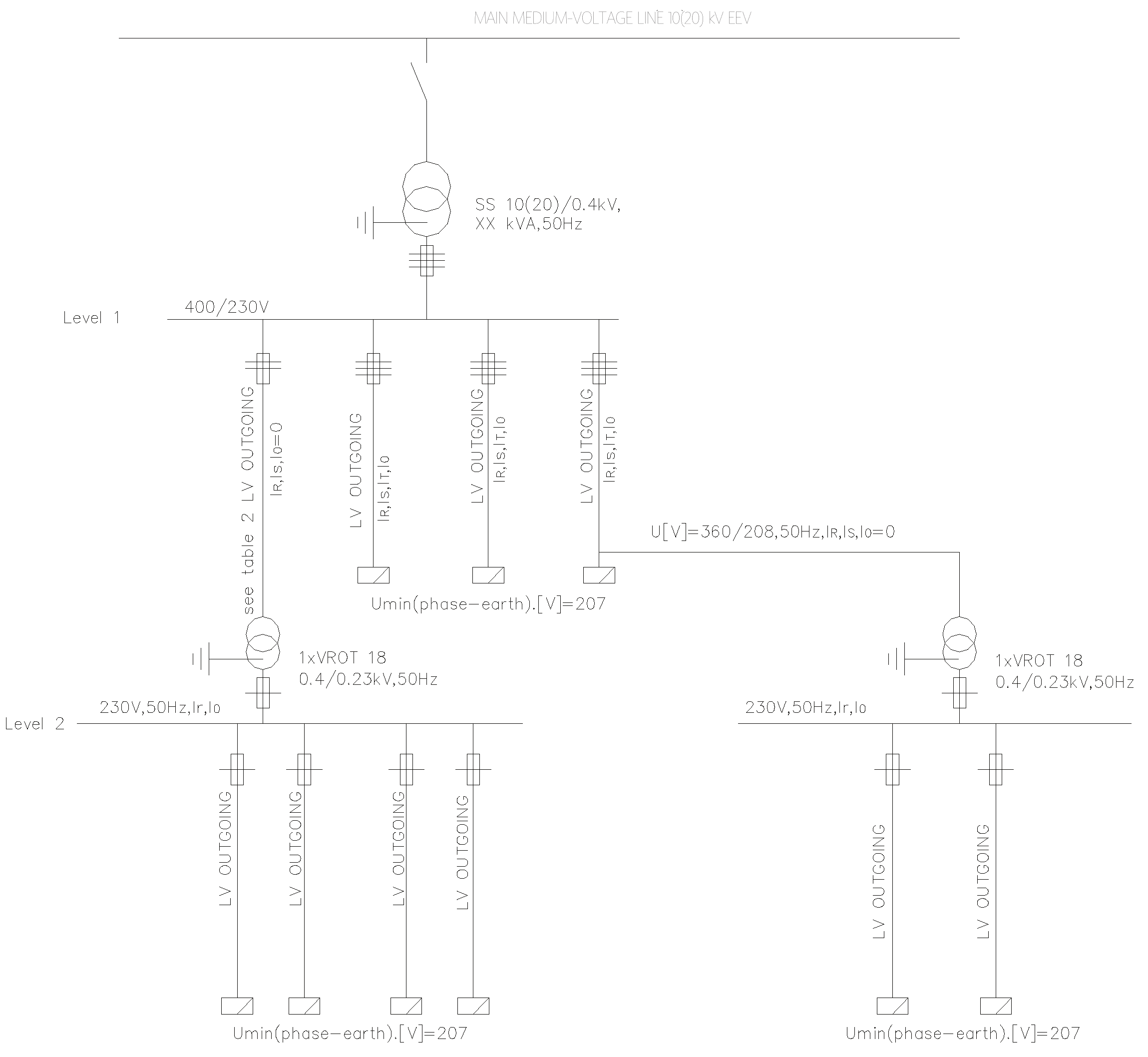
Voltage conditions along the low-voltage line
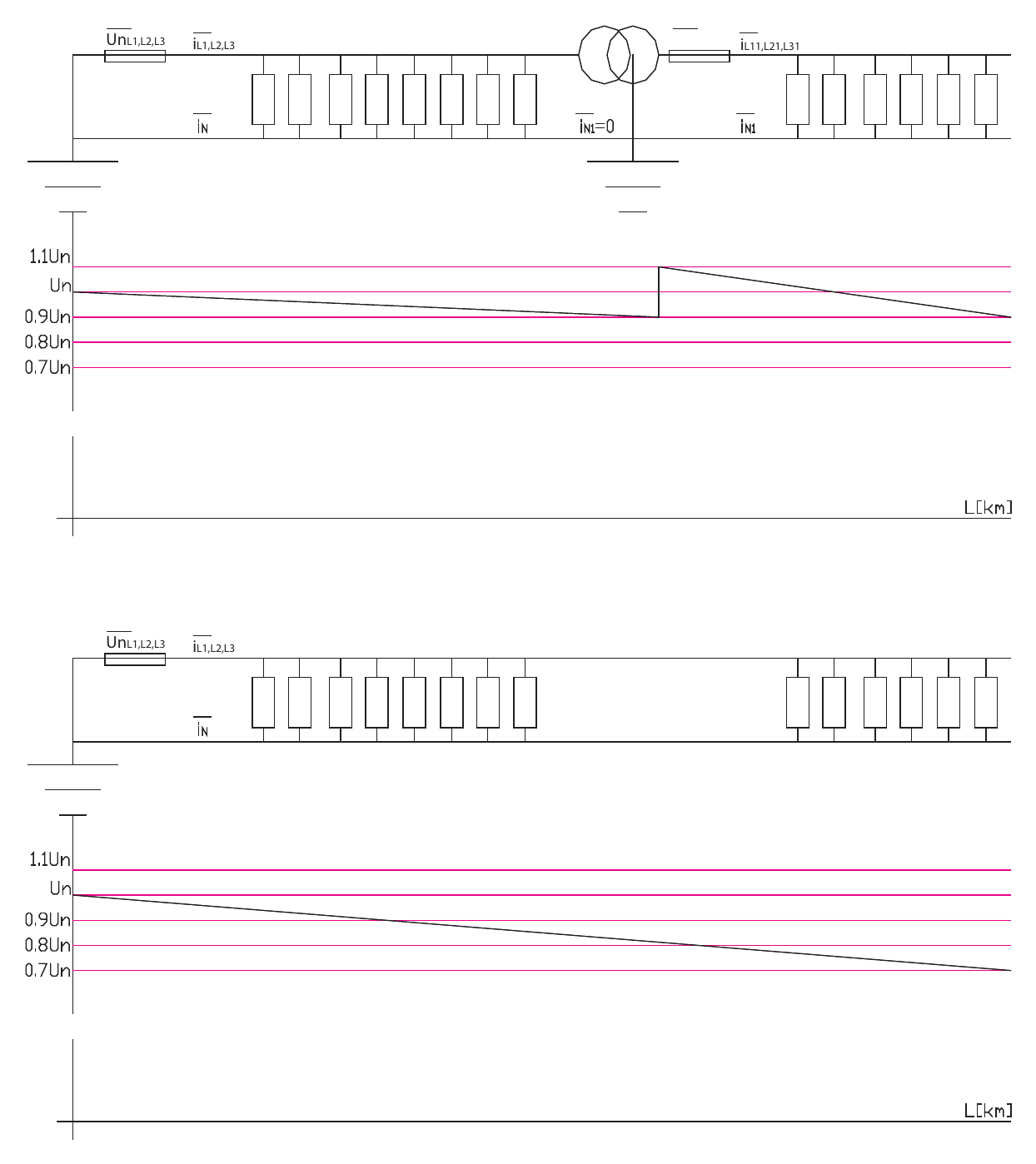
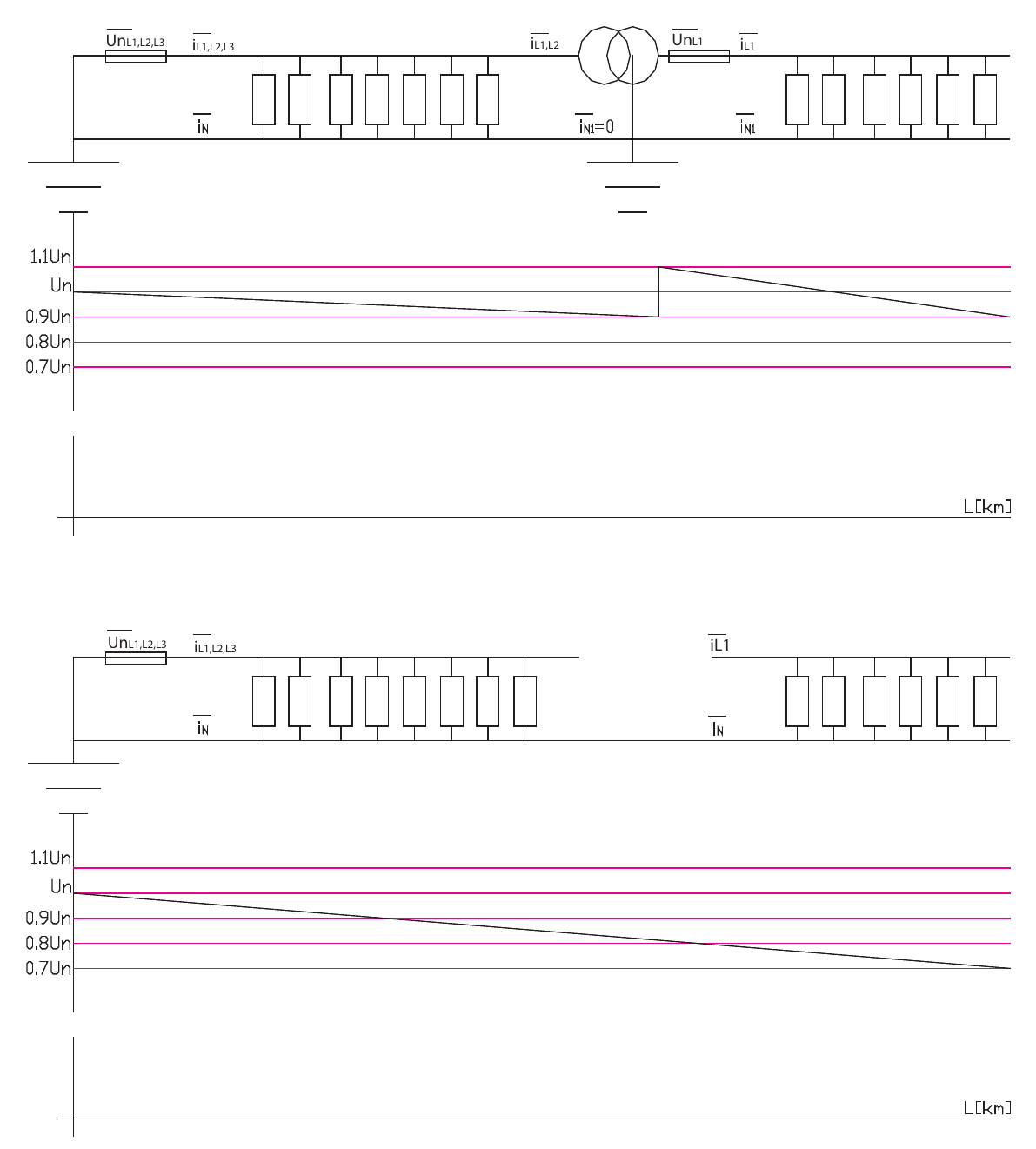
Click on a diagram to view it full size
Protection of consumers against overvoltage
Protection of consumers against overvoltage in the low-voltage distribution network in the event of faults caused by a short circuit between the phase and neutral conductors.
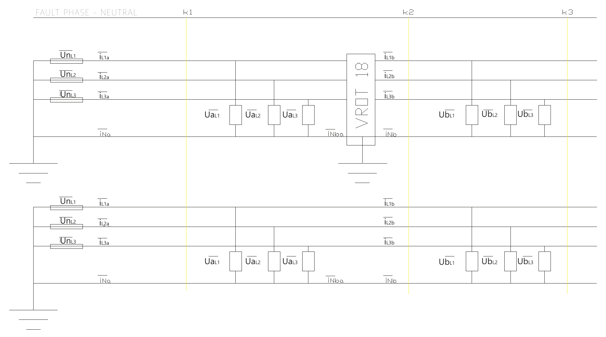
| Simulated fault location | WITH VROT 18 | WITHOUT VROT 18 | ||||
|---|---|---|---|---|---|---|
| k1 | k2 | k3 | k1 | k2 | k3 | |
| Conductor | X00-3x70+71.5 mm² | |||||
| Distance from the associated substation [m] | 200 | 600 | 1000 | 200 | 600 | 1000 |
| iRa [A] | 1224.04 | 709.81 | 757.60 | 1241.04 | 483.38 | 516.42 |
| URA [V] | 12.18 | 117.30 | 117.98 | 12.41 | 14.46 | 15.45 |
| iSa [A] | 39.18 | 710.18 | 758.00 | 61.40 | 58.45 | 58.70 |
| USA [V] | 297.36 | 117.15 | 117.80 | 293.42 | 279.35 | 280.51 |
| iTa [A] | 67.71 | 57.07 | 57.35 | 67.40 | 63.90 | 64.19 |
| UTA [V] | 293.54 | 212.74 | 213.91 | 292.63 | 277.41 | 278.69 |
| iNa [A] | 1163.54 | 14.24 | 14.4 | 1145.04 | 393.64 | 426.24 |
| iNab [A] | 0 | 0 | 0 | 43.42 | 442.91 | 475.65 |
| iRb [A] | 0 | 1176.73 | 1256.00 | 0 | 482.03 | 514.98 |
| URB [V] | 136.12 | 16.90 | 3.38 | 23.10 | 7.29 | 2.19 |
| iSb [A] | 29.08 | 24.37 | 24.50 | 36.40 | 34.66 | 34.80 |
| USB [V] | 234.36 | 196.46 | 195.21 | 275.85 | 281.05 | 277.39 |
| iTb [A] | 12.40 | 13.42 | 13.48 | 19.97 | 18.94 | 19.02 |
| UTB [V] | 135.07 | 196.60 | 198.22 | 280.88 | 279.53 | 278.49 |
| iNb [A] | 23.26 | 1173.43 | 1252.49 | 43.42 | 442.91 | 475.65 |
Field example
A VROT 18 device supplies a single-phase consumer area located 1500 m from the associated substation (SS 10(20)/0.4 kV, 250 kVA).
Before VROT 18 was installed, the consumer area had a consumption of 750 kWh/month.
After VROT 18 was installed, the consumer area had a consumption of 3,048 kWh/month – with voltage quality in accordance with IEC 60038/EN 50160.