Current transformers for railways
Description and application
DESCRIPTION: The main insulation of these transformers is cycloaliphatic resin. Their cores are made of high-quality cold-rolled magnetic steel sheet with an oriented magnetic structure. The secondary terminals are extended into a special housing that is resistant to the effects of dust and water and can be sealed. The transformers are manufactured with 1, 2, or 3 cores and the same number of independent secondary windings. Due to their construction, outdoor installation transformers can operate even under the most severe operating conditions in highly aggressive environments, because they feature a large creepage distance (>1300 mm) between the high-voltage terminal and the earthed metal parts of the transformer.
APPLICATION: These transformers are used to isolate measuring and protective devices from high voltage and to transform measuring currents to a value adapted to the measuring and protective devices. They are designed for outdoor installation in distribution switchgear plants with the highest network voltage up to 42 kV. They supply ammeters, current circuits of meters, protective relays, and other devices. Due to their large creepage distances, they are particularly suitable for the measurement and protection of railway networks, as they meet their most stringent requirements.
Installation, handling and maintenance
INSTALLATION: The transformers are mounted in a vertical position only. All connections on the primary and secondary sides must be clean and tightly fastened to prevent their overheating. One of the terminals of all secondary windings must be earthed (typically, this is terminal k, respectively S1). Care must be taken that the total burden of the connected measuring or protective devices, together with the losses in the connection cables, does not exceed the rated output of the current transformer. If the total burden of the connected devices, together with the burden originating from the connecting conductors, is less than one-quarter of the rated power of the winding, an additional burden should be inserted into that secondary circuit. With the additional burden, the current transformer will operate within its rated accuracy class. If, during operation, any of the secondary windings of the current transformer is not loaded, its terminals must be short-circuited.
During transformer installation, care must be taken not to interchange the primary or secondary connections. The current inlet on the primary winding is marked with K or P1, and the outlet with L or P2, while on the secondary winding, the inlet is marked with k or S1, and the outlet with l or S2. If the external dynamic forces of the primary connection lines are large (greater than 3.75 kN), support post insulators should be mounted near the current transformer. The transformers must be properly earthed at the designated location.
HANDLING AND MAINTENANCE: Regular maintenance is not mandatory for these transformers. From time to time, it should be checked whether all terminals are well secured, and the transformer should be cleaned if it is dirty. Ensure that the current transformer never operates with open secondary terminals, as a dangerously high voltage can appear across them, and serious damage to the insulation can occur. In the event of any breakdowns or short circuits in the plant, the current transformers should be tested to conclude whether they are still fully operational.
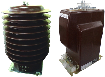
Current transformers for railways
Voltage: 25 kV, 35 kV | Mounting: Outdoor / Indoor | Insulation: Cycloaliphatic resin / Epoxy resin
Number of cores: 1-4 | Rated secondary current: 5 (or 1) A | Accuracy classes: 0,2; 0,5; 0,2S; 0,5S; 1; 3; 5P; 10P
When ordering, be sure to state the transformation ratio, rated output, accuracy class and instrument security factor or accuracy limit factor.
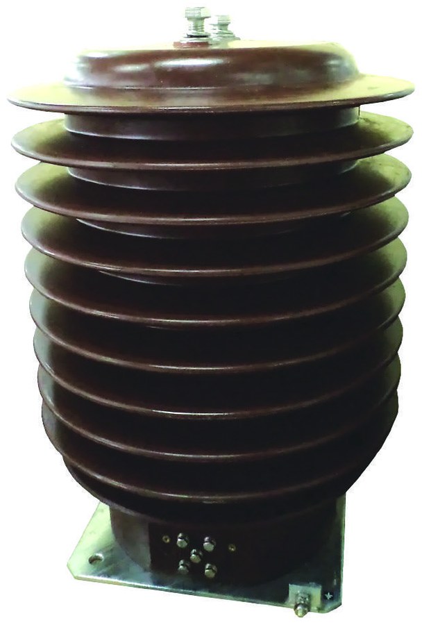
Current transformers for outdoor mounting
SMTSM 38*, SMTSM 38*L, SMTSM 38*b
Mounting: Outdoor | Voltage: 35 kV | 1-4 cores
As a standard, we manufacture these transformers for a short-time thermal current of 100In, but we can also produce them for higher thermal currents (up to 500In or more) depending on the transformation ratio, class, and output of the cores.
| TECHNICAL DATA | SMTSM 38 | SMTSM 38*L | SMTSM 38*b |
|---|---|---|---|
| Rated primary voltage (kV) | 35 | ||
| Highest voltage for equipment (eff.) (kV) | 38 (40,5) | ||
| Rated power frequency withstand voltage 1 min. (kV) | 70 (95) | ||
| Rated impulse withstand voltage 1.2/50 µs (kV) | 170 (200) | ||
| Creepage distance (mm) | 1327 | 1327 | 1296 |
| Mounting | Outdoor | ||
| Rated frequency (Hz) | 50/60 | ||
| Rated primary current (A) | 5 to 3000* or 2x5 to 2x600 | ||
| Rated secondary current (A) | 5 (or 1) | ||
| Rated accuracy class | 0,2; 0,5; 0,2S; 0,5S; 1; 3; 5P; 10P | ||
| Rated thermal current, 1 sec. | Ith = 100 In | ||
| Rated dynamic current | Idyn = 2,5 Ith | ||
| Rated continuous thermal current | Icth = 1,2 In | ||
| Number of cores | 1-4 | ||
| Rated core power (VA) | 5; 7,5; 10; 15; 30; 45*; 60* | ||
| Temperature class of insulation | E | ||
| Type of basic insulation | Cycloaliphatic resin | ||
| Valid standards | IEC 61869-1; IEC 61869-2 | ||
Dimensions and mass
| Type of transformer | Dimensions (mm) | Mass (kg) |
|---|---|---|
| SMTSM 38 | 520 | ~78 |
| SMTSM 38L | 520 | ~126 |
| SMTSM 38b | 486 | ~146 |
Designation examples:
SMTSM 3821L - transformer subtype SMTSM 38L, with two cores, primary-reconnectable;
SMTSM 3820 - transformer subtype SMTSM-38, with two cores, primary non-reconnectable;
SMTSM 3830b - transformer subtype SMTSM-38b, with three cores, primary non-reconnectable.
Reconnection can be performed from the primary and secondary sides, and sealing can be done on the secondary side.
These models can also be for more demanding conditions - BIL (40.5/95/200 kV), as they feature a larger creepage distance (≥31 mm/kV).
When ordering, be sure to state the transformation ratio, rated output, accuracy class, and instrument security factor or accuracy limit factor for each core.
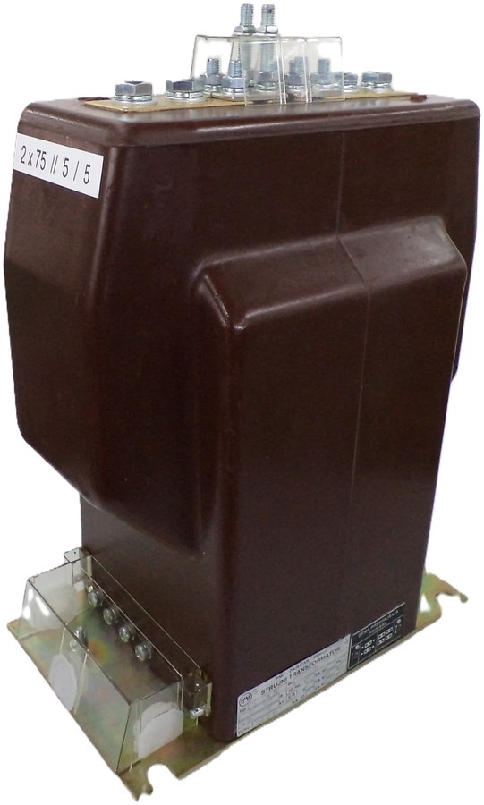
Current transformer for indoor mounting
STEM N-38*
Mounting: Indoor | Voltage: 25 kV | 1-4 cores
| TECHNICAL DATA | STEM-N 38* |
|---|---|
| Rated primary voltage (kV) | 25 |
| Maximum operating voltage (kV) | 29 |
| Lowest operating voltage (kV) | 19.5 |
| Highest voltage for equipment (r.m.s.) (kV) | 36 (42) |
| Power-frequency withstand voltage 50 Hz, 1 min. (kV) | 70 (95) |
| Impulse withstand voltage 1.2/50 µs (kV) | 170 (200) |
| Rated frequency (Hz) | 50/60 |
| Rated transformation ratio (A/A) | 5 to 1200 or 2x5 to 2x600 |
| Rated secondary current (A) | 5 (or 1) |
| Rated accuracy class | 0,2; 0,5; 0,2S; 0,5S; 1; 3; 5P; 10P |
| Rated short-time thermal current, 1 s | Ith = (100-1000)In |
| Rated dynamic current | Idyn = 2,5 Ith |
| Rated continuous thermal current | Icth = 1,2 In |
| Number of cores | 1-4 |
| Rated core output (VA) | 5; 7,5; 10; 15; 30 |
| Instrument security factor / Accuracy limit factor | 5; 10 / 5; 10; 15; 20; 30 |
| Insulation temperature class | E/B |
| Sealing capability | On the primary and secondary side |
| Type of mounting | Indoor |
| Mass (kg) | 36 |
| Type of main insulation | Epoxy resin |
| Valid standards | IEC 61869-1; IEC 61869-2 |