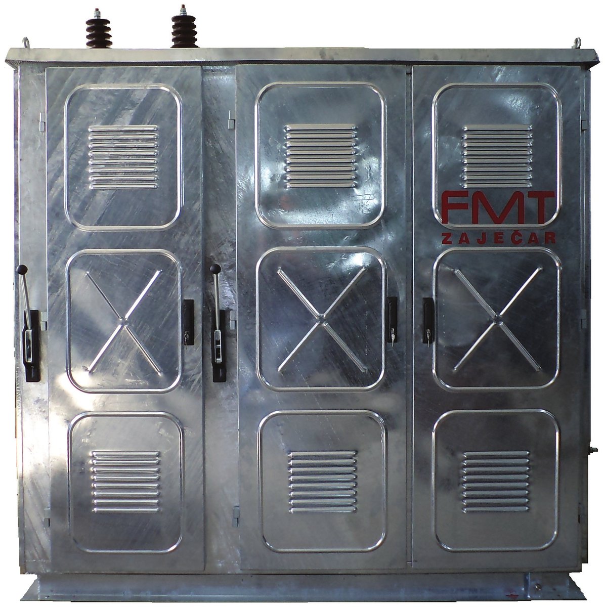
Neutral earthing resistors
Application and description
APPLICATION
The resistors are intended for earthing the neutral (star) point in medium-voltage networks. In order to limit the fault current at the neutral point, a resistor must be connected between the neutral point and the earthing system of the substation.
OPERATION
Under normal operating conditions the neutral point is at earth potential, so the currents flowing through it are negligible. These are currents caused by higher harmonics and phase asymmetry. If a phase-to-earth fault occurs, large currents flow through the neutral point, and the task of the connected resistor is to limit the current to the prescribed value until the protection operates. The voltage across the resistor terminals can rise up to the network voltage level. The resistor withstands an unlimited number of operating cycles at ambient temperatures up to 40°C.
DESIGN
The resistors are installed in a metal enclosure made of hot-dip galvanized pickled steel sheet. The enclosure can also be made entirely of stainless steel, or of a combination of stainless steel and hot-dip galvanized steel sheet.
The resistors themselves are metallic and cooled by natural air circulation. They are made of high-quality steel sheet with a low temperature coefficient and high specific and mechanical resistance. Each resistor element is cut in a special way, which provides the appropriate resistance and the ability to conduct current continuously. On its upper side, the resistor element has a reinforcement insulated from the element itself. These resistors are assembled into resistor systems which, together with supporting insulators, form blocks. All of them are tested as high-voltage equipment. The system is equipped with a suitable current transformer at the input towards the neutral point, used for connecting protection and signalling devices.
Special requirements
- Adjustment of the current transformer characteristics.
- Adjustment of the rated operating duty.
- Resistor without a current transformer at the input. In that case we supply a current transformer for outdoor mounting (type ATM or ATMS), which is mounted directly in front of the resistor, on the neutral-point side.
- Resistor with a current transformer at the output towards earth.
- Resistor with a heating element for heating the resistor when operating at low temperatures with snowfall.
- Resistor with a cable entry from below.
- Disconnectors installed in the resistor enclosure, or in a separate enclosure.
RESISTORS WITHOUT DISCONNECTORS
OVN-6/300, OVN-12/300, OVN-21/300
Sketch
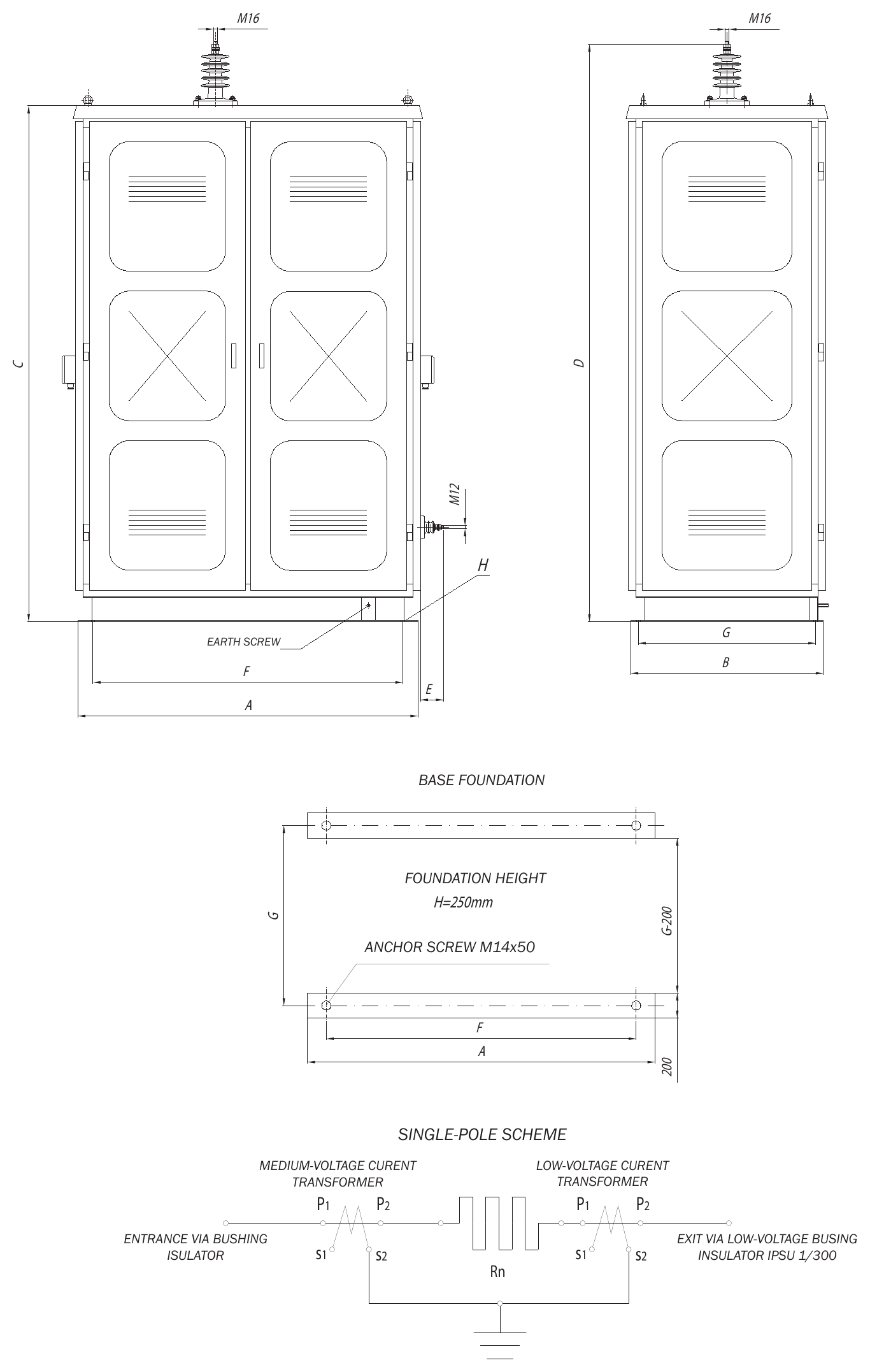
Click the sketch to view it full size
Dimensions – OVN-6/300, OVN-12/300, OVN-21/300
| Type of resistor | Dimensions (mm) | |||||||
|---|---|---|---|---|---|---|---|---|
| A | B | C | D | E | F | G | H | |
| OVN-6/300 | 1360 | 770 | 2065 | 2212 | 90 | 1240 | 710 | Ø17 |
| OVN-12/300 | 1360 | 1500 | 2197 | 2422 | 90 | 1240 | 1440 | Ø17 |
| OVN-21/300 | 2680 | 1500 | 2197 | 2570 | 90 | 2480 | 1440 | Ø17 |
Technical characteristics – OVN-6/300, OVN-12/300, OVN-21/300
| TYPE OF METAL RESISTOR | OVN-6/300 | OVN-12/300 | OVN-21/300 |
|---|---|---|---|
| Rated network voltage (kV) | 10 | 20 | 35 |
| Rated resistor voltage (kV) | 6 | 12 | 21 |
| Rated resistor current (A) | 300 | 300 | 300 |
| Rated operating duty | 300A/5s 20A/10min 5A/continuous | 300A/5s 20A/10min 5A/continuous | 300A/5s 20A/10min 5A/continuous |
| Number of resistor blocks | 5 | 10 | 18 |
| Rated resistance of the resistor block (Ω) | 4±5% | 4±5% | 4±5% |
| Rated resistance of the resistor at +20ºC (Ω) | 20±5% | 40±5% | 70±5% |
| Power-frequency test voltage, 1 min, 50 Hz (kV) | 12 | 24 | 42 |
| Degree of mechanical protection | IP23 / IP33 | ||
| Applicable standards | IEEE 32, IEC 60060-1, IEC 62271-1, IEC 60529, IEC 60071-1 | ||
| Bushing insulator at the input* | IPSU-12/630 | IPSU-24/630 | IPSU-38/630 |
| Medium-voltage measuring current transformer (input)* | STEM-N-1210 | STEM-N-2410 | STEM-N-3810 |
| Low-voltage measuring current transformer (output)* | ST-081: 0.72 kV, 50/5 A/A, 5 VA, 5P10 | ||
| Mass (kg) | 440 | 850 | 1420 |
Click an insulator or transformer designation to open its page in a new tab.
The characteristics of the current transformers are adapted to the customer's requirements (the resistor can also be supplied without transformers).
The input can also be a cable entry from below (on customer request).
* Types of insulators and measuring current transformers are in accordance with the recommendations of EPS (Electric Power Industry of Serbia).
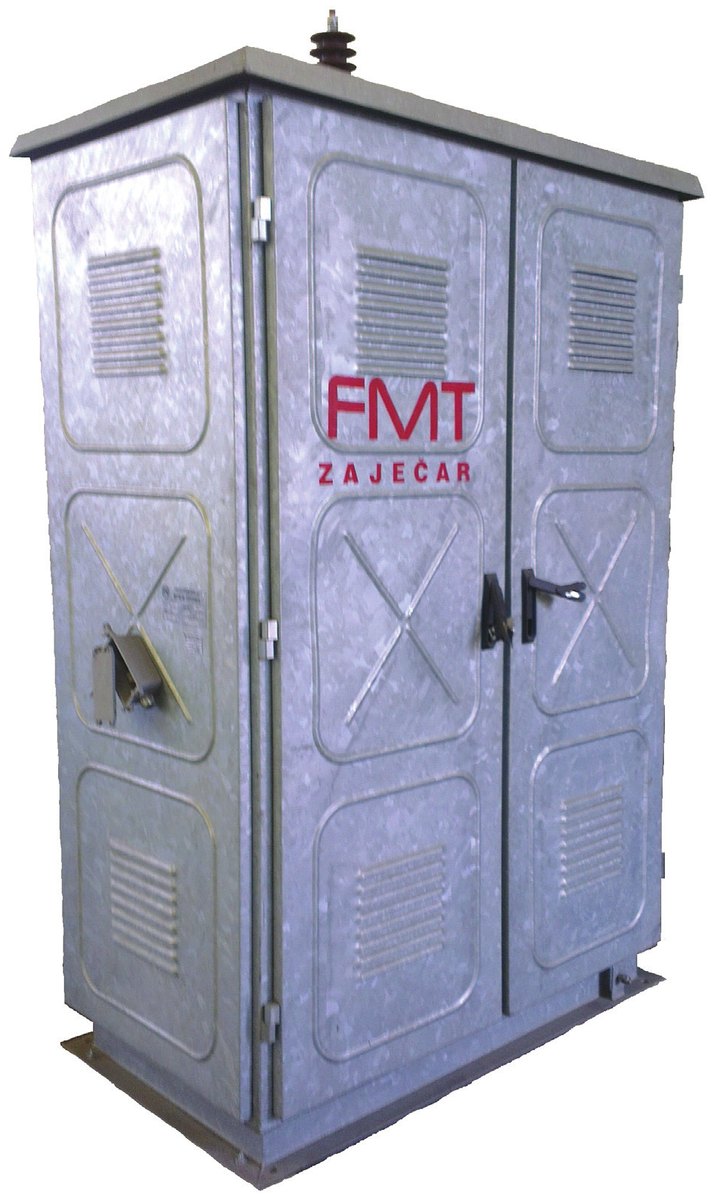
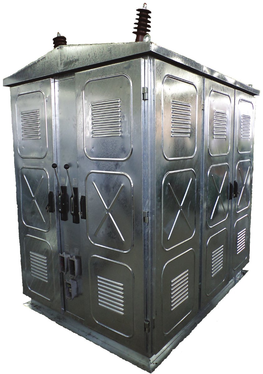
Photo – OVN-6/300
RESISTORS WITH DISCONNECTORS
OVNR1-6/300, OVNR1-12/300, OVNR1-21/300 (one disconnector)
OVNR2-6/300, OVNR2-12/300, OVNR2-21/300 (two disconnectors)
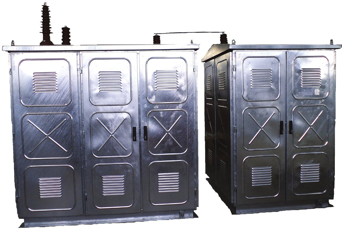
The disconnectors can be installed:
- In the metal enclosure of the resistor.
The disconnectors are equipped with a manual operating mechanism, a linkage and, if required, an auxiliary signalling switch (with normally open and normally closed contacts), which increases the overall dimensions of the enclosure. - In a separate metal enclosure.
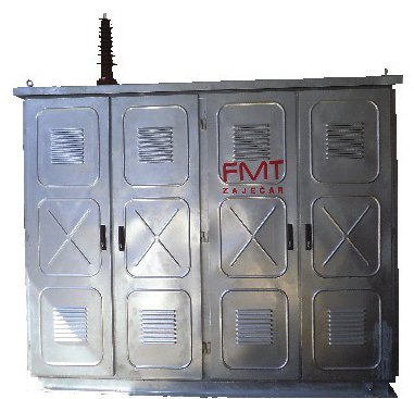
The dimensions of the separate metal enclosure depend on the type of disconnector and on the voltage level for which it is intended. Because of their size, resistors OVNR1-21/300 and OVNR2-21/300 are made of two enclosures (an input section with the disconnectors and an output section), interconnected by a copper bar (as can be seen in the attached photo).
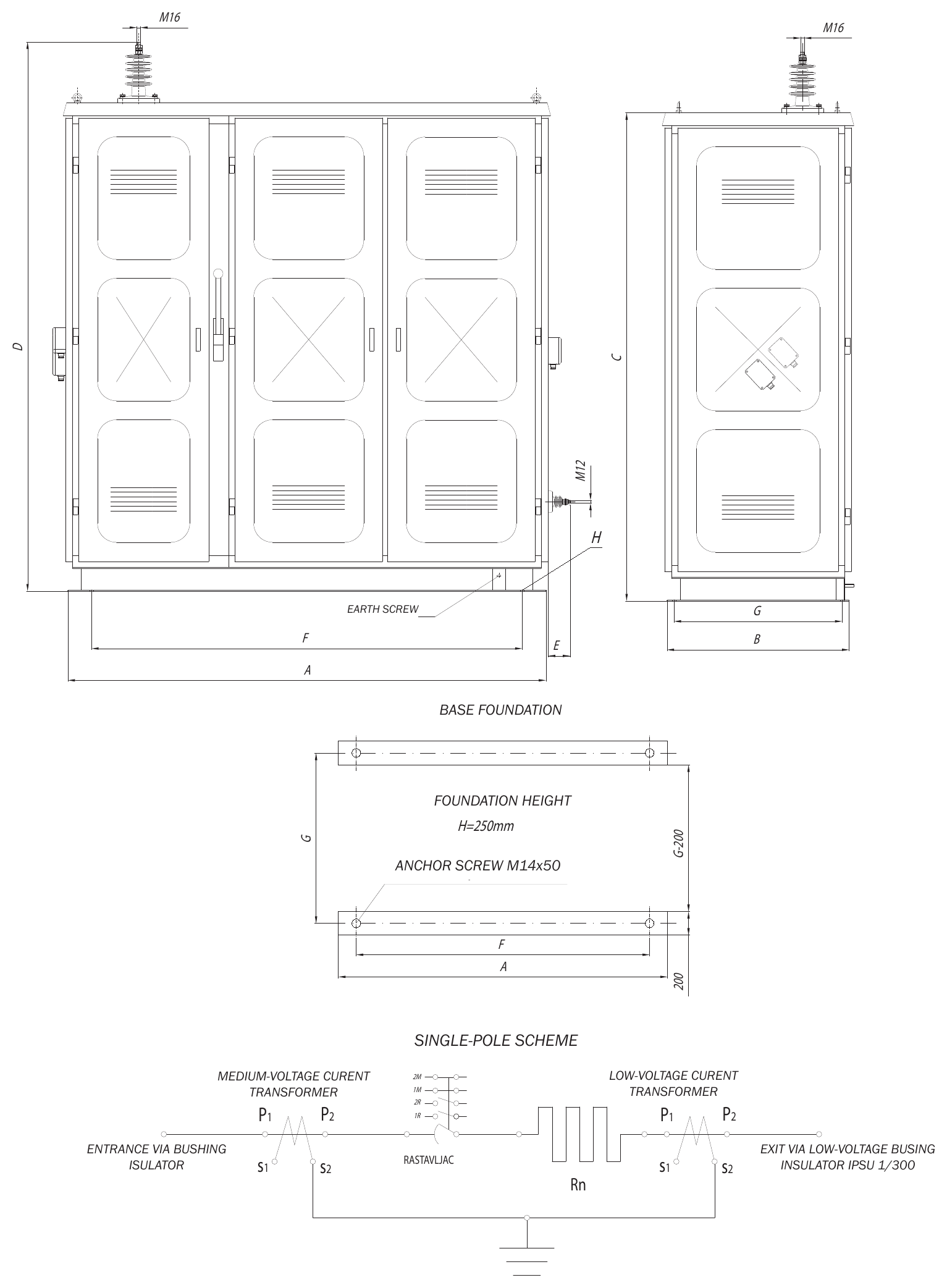
Sketch
Click the sketch to view it full size
Dimensions – OVNR1-* and OVNR2-*
| Type of resistor | Dimensions (mm) | |||||||
|---|---|---|---|---|---|---|---|---|
| A | B | C | D | E | F | G | H | |
| OVNR1-6/300 | 2020 | 770 | 2065 | 2212 | 90 | 1820 | 710 | Ø17 |
| OVNR2-6/300 | 2150 | 770 | 2065 | 2212 | 90 | 1950 | 710 | Ø17 |
| OVNR1-12/300 | 2020 | 1500 | 2197 | 2422 | 90 | 1820 | 1440 | Ø17 |
| OVNR2-12/300 | 2020 | 1500 | 2197 | 2422 | 90 | 1820 | 1440 | Ø17 |
| OVNR1-21/300 | 2020 | 1500 | 2197 | 2570 | 90 | 1820 | 1440 | Ø17 |
| 1360 | 1500 | 2197 | 2422 | 90 | 1240 | 1440 | Ø17 | |
| OVNR2-21/300 | 2130 | 1500 | 2197 | 2570 | 90 | 1930 | 1440 | Ø17 |
| 1360 | 1500 | 2197 | 2422 | 90 | 1240 | 1440 | Ø17 | |
Resistors OVNR1-21/300 and OVNR2-21/300 consist of two enclosures, so the dimensions of both enclosures are given.
Technical characteristics – OVNR1-* and OVNR2-*
| TYPE OF METAL RESISTOR | OVNR1-6/300 | OVNR2-6/300 | OVNR1-12/300 | OVNR2-12/300 | OVNR1-21/300 | OVNR2-21/300 |
|---|---|---|---|---|---|---|
| Rated network voltage (kV) | 10 | 10 | 20 | 20 | 35 | 35 |
| Rated resistor voltage (kV) | 6 | 6 | 12 | 12 | 21 | 21 |
| Rated resistor current (A) | 300 | 300 | 300 | 300 | 300 | 300 |
| Rated operating duty | 300A/5s 20A/10min 5A/continuous | 300A/5s 20A/10min 5A/continuous | 300A/5s 20A/10min 5A/continuous | 300A/5s 20A/10min 5A/continuous | 300A/5s 20A/10min 5A/continuous | 300A/5s 20A/10min 5A/continuous |
| Number of resistor blocks | 5 | 5 | 10 | 10 | 18 | 18 |
| Rated resistance of the resistor block (Ω) | 4±5% | 4±5% | 4±5% | 4±5% | 4±5% | 4±5% |
| Rated resistance of the resistor at +20ºC (Ω) | 20±5% | 20±5% | 40±5% | 40±5% | 70±5% | 70±5% |
| Power-frequency test voltage, 50 Hz, 1 min (kV) | 12 | 12 | 24 | 24 | 42 | 42 |
| Degree of mechanical protection | IP23 / IP33 | |||||
| Applicable standards | IEEE 32, SRPS EN 60060-1, SRPS EN 62271-1, SRPS EN 60529, SRPS EN IEC 60071-1 | |||||
| Bushing insulator at the input* | IPSU-12/630 | IPSU-12/630 | IPSU-24/630 | IPSU-24/630 | IPSU-38/630 | IPSU-38/630 |
| Medium-voltage measuring current transformer (input)* | STEM-N-1210 | STEM-N-1210 | STEM-N-2410 | STEM-N-2410 | STEM-N-3810 | STEM-N-3810 |
| Low-voltage measuring current transformer (output)* | ST-081: 0.72 kV, 50/5 A/A, 5 VA, 5P10 | |||||
| Disconnector | JRUK-12/630 | JRUK-12/630 | JRUK-24/630 | JRUK-24/630 | JRUK-38/630 | JRUK-38/630 |
| Mass (kg) | 600 | 650 | 1020 | 1075 | 1816 | 1856 |
Click an insulator or transformer designation to open its page in a new tab.
The characteristics of the current transformers are adapted to the customer's requirements (the resistor can also be supplied without transformers).
The input can also be a cable entry from below (on customer request).
R1 in the type designation means that the resistor has 1 disconnector, and R2 – 2 disconnectors.
* Types of insulators and measuring current transformers are in accordance with the recommendations of EPS (Electric Power Industry of Serbia).
Photo – OVNR2-6/300