Support Insulators
Purpose and description
PURPOSE: Support insulators are used as load-bearing elements for bus-bars in switchgear cabinets. They can also be used as supporting elements for terminals and winding leads of transformers and electric motors. Thanks to the properties of epoxy resin, they can operate under all service conditions, including tropical climates, and are particularly suited to locations requiring resistance to moisture, chemical influences, impulse voltages and breaking forces. Because of these properties, in addition to the applications listed, they are suitable for use in the mining and chemical industries, as well as for installation on ships.
DESCRIPTION: Support insulators are made with a basic insulation of epoxy resin, temperature class E/B (maximum temperature 125°C, with a maximum ambient temperature of 40°C). The cast-in metal parts are made of brass, making them resistant to atmospheric influences.
According to breaking force, support insulators are divided into class A insulators (3,75 kN), class B (7,5 kN) and class C (12,5 kN). Detailed technical characteristics for each type of insulator are given in the table next to each insulator.
Mounting and maintenance
MOUNTING: The insulator is mounted using the cast-in brass sleeves or bolts, depending on the type of insulator. When mounting, pay attention to bolt tightening torque, since tightening beyond the permitted value may pull out the sleeve, break the bolt, or crack the insulator.
MAINTENANCE: During operation, almost no maintenance is required. It is only necessary, during regular annual overhauls, to clean them of dirt and tighten the mounting screws and connection joints, especially for insulators installed in machines whose operation is accompanied by significant vibration.
Filters
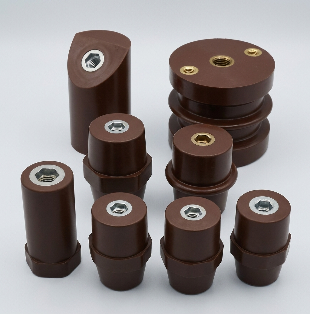
Low-voltage support insulators
Voltage: up to 1 kV | Mounting: Indoor | Insulation: Epoxy resin
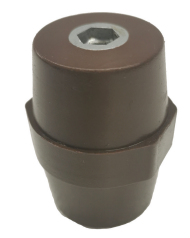
Low-voltage support insulators
OK/S*
Dimensions and characteristics
| Type | Dimensions (mm) | Packaging (pcs.) | ||||||
|---|---|---|---|---|---|---|---|---|
| H | SW | D1 | Um (V) | M | A | F (kN) | ||
| OK/S 3030 - M6 | 30 | 30 | 26 | 600 | M6 | 8 | 1.25 | 80 |
| OK/S 3030 - M8 | 30 | 30 | 26 | 600 | M8 | 7 | 1.25 | 80 |
| OK/S 3235 - M6 | 35 | 32 | 28 | 1000 | M6 | 9 | 2.25 | 64 |
| OK/S 3235 - M8 | 35 | 32 | 28 | 1000 | M8 | 10 | 2.25 | 64 |
| OK/S 3235 - M10 | 35 | 32 | 28 | 1000 | M10 | 10 | 2.25 | 64 |
| OK/S 4135 - M6 | 35 | 41 | 35 | 1000 | M6 | 9 | 4 | 36 |
| OK/S 4135 - M8 | 35 | 41 | 35 | 1000 | M8 | 9 | 4 | 36 |
| OK/S 4135 - M10 | 35 | 41 | 35 | 1000 | M10 | 10 | 4 | 36 |
| OK/S 4040 - M8 | 40 | 40 | 30 | 1000 | M8 | 11 | 4 | 100 |
| OK/S 4040 - M10 | 40 | 40 | 30 | 1000 | M10 | 12 | 4 | 100 |
| OK/S 4040 - M12 | 40 | 40 | 30 | 1000 | M12 | 10 | 4 | 100 |
| OK/S 4145 - M6 | 45 | 41 | 35 | 1500 | M6 | 12 | 4 | 27 |
| OK/S 4145 - M8 | 45 | 41 | 35 | 1500 | M8 | 12 | 4 | 27 |
| OK/S 4145 - M10 | 45 | 41 | 35 | 1500 | M10 | 12 | 4 | 27 |
| OK/S 4145 - M12 | 45 | 41 | 35 | 1500 | M12 | 12 | 4 | 27 |
| OK/S 3650 - M8 | 50 | 36 | 29 | 2000 | M8 | 12 | 2.25 | 36 |
| OK/S 3650 - M10 | 50 | 36 | 29 | 2000 | M10 | 12 | 2.25 | 36 |
| OK/S 3650 - M12 | 50 | 36 | 29 | 2000 | M12 | 13 | 2.25 | 36 |
| OK/S 5560 - M8 | 60 | 55 | 40 | 2000 | M8 | 20 | 3.5 | 25 |
| OK/S 5560 - M10 | 60 | 55 | 40 | 2000 | M10 | 21 | 3.5 | 25 |
| OK/S 5560 - M12 | 60 | 55 | 40 | 2000 | M12 | 20 | 3.5 | 25 |
| OK/S 4165 - M8 | 65 | 41 | 35 | 3000 | M8 | 17 | 3.5 | 22 |
| OK/S 4165 - M10 | 65 | 41 | 35 | 3000 | M10 | 19 | 3.5 | 22 |
| OK/S 4165 - M12 | 65 | 41 | 35 | 3000 | M12 | 19 | 3.5 | 22 |
| OK/S 5070 - M8 | 70 | 50 | 36 | 5000 | M8 | 19 | 4.5 | 12 |
| OK/S 5070 - M10 | 70 | 50 | 36 | 5000 | M10 | 19 | 4.5 | 12 |
| OK/S 5070 - M12 | 70 | 50 | 36 | 5000 | M12 | 19 | 4.5 | 12 |
| OK/S 6575 - M12 | 75 | 65 | 52 | 5000 | M12 | 18 | 7.5 | 8 |
| OK/S 6575 - M16 | 75 | 65 | 52 | 5000 | M16 | 23 | 7.5 | 8 |
| Technical data | OK/S* |
|---|---|
| Colour | Brown |
| Standard | IEC 60273:1990; IEC 60660:1999 |
| Mounting | Indoor |
| Temperature resistance (°C) | -40°C to +125°C |
| Type of basic insulation | Epoxy resin |
NOTE: OK/S* type insulators have excellent electrical and mechanical characteristics and can be used in extreme operating conditions such as high ambient temperatures, as well as when in contact with corrosive substances and vibration. The hexagon in the middle is provided for a wrench, for easier mounting and fixing of the insulator. OK/S* type insulators are made of epoxy resin, which contributes to environmental and human health protection compared to similar materials such as glass-fibre-reinforced polyester.
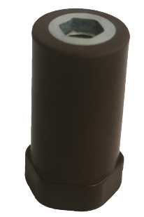
Low-voltage support insulators
OK/D 21*
Dimensions and characteristics
| Type | Dimensions (mm) | Packaging (pcs.) | ||||||
|---|---|---|---|---|---|---|---|---|
| H | SW | D1 | Um (V) | M | A | F (kN) | ||
| OK/D 2116 - M4 | 16 | 21 | 20 | 220 | M4 | 4 | 3 | 200 |
| OK/D 2116 - M5 | 16 | 21 | 20 | 220 | M5 | 4 | 3 | 200 |
| OK/D 2116 - M6 | 16 | 21 | 20 | 220 | M6 | 4 | 3 | 100 |
| OK/D 2116 - M8 | 16 | 21 | 20 | 220 | M8 | 4 | 3 | 150 |
| OK/D 2120 - M5 | 20 | 21 | 20 | 400 | M5 | 5 | 2.5 | 200 |
| OK/D 2120 - M6 | 20 | 21 | 20 | 400 | M6 | 5 | 2.5 | 100 |
| OK/D 2120 - M8 | 20 | 21 | 20 | 400 | M8 | 5 | 2.5 | 200 |
| OK/D 2125 - M5 | 25 | 21 | 20 | 500 | M5 | 6 | 2 | 150 |
| OK/D 2125 - M6 | 25 | 21 | 20 | 500 | M6 | 6 | 2 | 150 |
| OK/D 2125 - M8 | 25 | 21 | 20 | 500 | M8 | 6 | 2 | 150 |
| OK/D 2130 - M5 | 30 | 21 | 20 | 600 | M5 | 7 | 2 | 140 |
| OK/D 2130 - M6 | 30 | 21 | 20 | 600 | M6 | 7 | 2 | 140 |
| OK/D 2130 - M8 | 30 | 21 | 20 | 600 | M8 | 7 | 2 | 140 |
| OK/D 2135 - M6 | 35 | 21 | 20 | 600 | M6 | 7 | 1.5 | 120 |
| OK/D 2140 - M6 | 40 | 21 | 20 | 600 | M6 | 9 | 1.5 | 110 |
| OK/D 2140 - M8 | 40 | 21 | 20 | 600 | M8 | 10 | 1.5 | 110 |
| OK/D 2145 - M6 | 45 | 21 | 20 | 750 | M6 | 9 | 1 | 100 |
| OK/D 2145 - M8 | 45 | 21 | 20 | 750 | M8 | 10 | 1 | 100 |
| OK/D 2150 - M6 | 50 | 21 | 20 | 750 | M6 | 10 | 1 | 80 |
| OK/D 2150 - M8 | 50 | 21 | 20 | 750 | M8 | 10 | 1 | 80 |
| OK/D 2160 - M6 | 60 | 21 | 20 | 750 | M6 | 9 | 1 | 70 |
| OK/D 2160 - M8 | 60 | 21 | 20 | 750 | M8 | 9 | 1 | 70 |
| Technical data | OK/D 21* |
|---|---|
| Colour | Brown |
| Standard | IEC 60273:1990; IEC 60660:1999 |
| Mounting | Indoor |
| Temperature resistance (°C) | -40°C to +125°C |
| Type of basic insulation | Epoxy resin |
NOTE: OK/D 21* type insulators have excellent electrical and mechanical characteristics and can be used in extreme operating conditions such as high ambient temperatures, as well as when in contact with corrosive substances and vibration. The hexagon on the bottom is provided for a wrench, for easier mounting and fixing of the insulator. OK/D 21* type insulators are made of epoxy resin, which contributes to environmental and human health protection compared to similar materials such as glass-fibre-reinforced polyester.
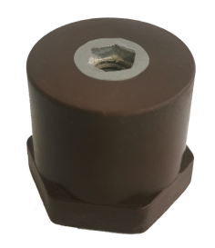
Low-voltage support insulators
OK/D 30*
Dimensions and characteristics
| Type | Dimensions (mm) | Packaging (pcs.) | ||||||
|---|---|---|---|---|---|---|---|---|
| H | SW | D1 | Um (V) | M | A | F (kN) | ||
| OK/D 3030 - M6 | 30 | 30 | 30 | 750 | M6 | 9 | 4.5 | 80 |
| OK/D 3030 - M8 | 30 | 30 | 30 | 750 | M8 | 9 | 4.5 | 80 |
| OK/D 3030 - M10 | 30 | 30 | 30 | 750 | M10 | 9 | 4.5 | 80 |
| OK/D 3035 - M6 | 35 | 30 | 30 | 1000 | M6 | 9 | 4.5 | 64 |
| OK/D 3035 - M8 | 35 | 30 | 30 | 1000 | M8 | 9 | 4.5 | 64 |
| OK/D 3035 - M10 | 35 | 30 | 30 | 1000 | M10 | 9 | 4.5 | 64 |
| OK/D 3040 - M6 | 40 | 30 | 30 | 1000 | M6 | 12 | 3 | 60 |
| OK/D 3040 - M8 | 40 | 30 | 30 | 1000 | M8 | 12 | 3 | 60 |
| OK/D 3040 - M10 | 40 | 30 | 30 | 1000 | M10 | 12 | 3 | 60 |
| OK/D 3045 - M6 | 45 | 30 | 30 | 1000 | M6 | 12 | 2.5 | 48 |
| OK/D 3045 - M8 | 45 | 30 | 30 | 1000 | M8 | 12 | 2.5 | 48 |
| OK/D 3045 - M10 | 45 | 30 | 30 | 1000 | M10 | 13 | 2.5 | 48 |
| OK/D 3050 - M6 | 50 | 30 | 30 | 1500 | M6 | 12 | 2 | 48 |
| OK/D 3050 - M8 | 50 | 30 | 30 | 1500 | M8 | 13 | 2 | 48 |
| OK/D 3050 - M10 | 50 | 30 | 30 | 1500 | M10 | 12 | 2 | 48 |
| OK/D 3055 - M6 | 55 | 30 | 30 | 1500 | M6 | 12 | 1.5 | 40 |
| OK/D 3055 - M8 | 55 | 30 | 30 | 1500 | M8 | 11 | 1.5 | 40 |
| OK/D 3060 - M6 | 60 | 30 | 30 | 1500 | M6 | 12 | 1.5 | 40 |
| OK/D 3060 - M8 | 60 | 30 | 30 | 1500 | M8 | 16 | 1.5 | 40 |
| OK/D 3060 - M10 | 60 | 30 | 30 | 1500 | M10 | 20 | 1.5 | 40 |
| OK/D 3065 - M8 | 65 | 30 | 30 | 1500 | M8 | 18 | 1 | 32 |
| OK/D 3070 - M6 | 70 | 30 | 30 | 1500 | M6 | 14 | 1 | 32 |
| OK/D 3070 - M8 | 70 | 30 | 30 | 1500 | M8 | 18 | 1 | 32 |
| OK/D 3070 - M10 | 70 | 30 | 30 | 1500 | M10 | 18 | 1 | 32 |
| Technical data | OK/D 30* |
|---|---|
| Colour | Brown |
| Standard | IEC 60273:1990; IEC 60660:1999 |
| Mounting | Indoor |
| Temperature resistance (°C) | -40°C to +125°C |
| Type of basic insulation | Epoxy resin |
NOTE: OK/D 30* type insulators have excellent electrical and mechanical characteristics and can be used in extreme operating conditions such as high ambient temperatures, as well as when in contact with corrosive substances and vibration. The hexagon on the bottom is provided for a wrench, for easier mounting and fixing of the insulator. OK/D 30* type insulators are made of epoxy resin, which contributes to environmental and human health protection compared to similar materials such as glass-fibre-reinforced polyester.
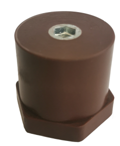
Low-voltage support insulators
OK/D 41*
Dimensions and characteristics
| Type | Dimensions (mm) | Packaging (pcs.) | ||||||
|---|---|---|---|---|---|---|---|---|
| H | SW | D1 | Um (V) | M | A | F (kN) | ||
| OK/D 4130 - M8 | 30 | 41 | 40 | 750 | M8 | 8 | 7.5 | 45 |
| OK/D 4130 - M10 | 30 | 41 | 40 | 750 | M10 | 9 | 7.5 | 45 |
| OK/D 4135 - M8 | 35 | 41 | 40 | 750 | M8 | 9 | 7 | 36 |
| OK/D 4135 - M10 | 35 | 41 | 40 | 750 | M10 | 9 | 7 | 36 |
| OK/D 4140 - M8 | 40 | 41 | 40 | 1000 | M8 | 12 | 7 | 27 |
| OK/D 4140 - M10 | 40 | 41 | 40 | 1000 | M10 | 12 | 7 | 27 |
| OK/D 4140 - M12 | 40 | 41 | 40 | 1000 | M12 | 12 | 7 | 27 |
| OK/D 4145 - M8 | 45 | 41 | 40 | 1000 | M8 | 13 | 7 | 27 |
| OK/D 4145 - M10 | 45 | 41 | 40 | 1000 | M10 | 12 | 7 | 27 |
| OK/D 4150 - M8 | 50 | 41 | 40 | 1500 | M8 | 12 | 5 | 27 |
| OK/D 4150 - M10 | 50 | 41 | 40 | 1500 | M10 | 13 | 5 | 27 |
| OK/D 4150 - M12 | 50 | 41 | 40 | 1500 | M12 | 11 | 5 | 27 |
| OK/D 4155 - M10 | 55 | 41 | 40 | 1500 | M10 | 12 | 4 | 18 |
| OK/D 4160 - M8 | 60 | 41 | 40 | 1500 | M8 | 18 | 3.5 | 18 |
| OK/D 4160 - M10 | 60 | 41 | 40 | 1500 | M10 | 18 | 3.5 | 18 |
| OK/D 4160 - M12 | 60 | 41 | 40 | 1500 | M12 | 18 | 3.5 | 18 |
| OK/D 4165 - M10 | 65 | 41 | 40 | 1500 | M10 | 18 | 3.5 | 18 |
| OK/D 4170 - M8 | 70 | 41 | 40 | 1500 | M8 | 18 | 3 | 18 |
| OK/D 4170 - M10 | 70 | 41 | 40 | 1500 | M10 | 18 | 3 | 18 |
| Technical data | OK/D 41* |
|---|---|
| Colour | Brown |
| Standard | IEC 60273:1990; IEC 60660:1999 |
| Mounting | Indoor |
| Temperature resistance (°C) | -40°C to +125°C |
| Type of basic insulation | Epoxy resin |
NOTE: OK/D 41* type insulators have excellent electrical and mechanical characteristics and can be used in extreme operating conditions such as high ambient temperatures, as well as when in contact with corrosive substances and vibration. The hexagon on the bottom is provided for a wrench, for easier mounting and fixing of the insulator. OK/D 41* type insulators are made of epoxy resin, which contributes to environmental and human health protection compared to similar materials such as glass-fibre-reinforced polyester.
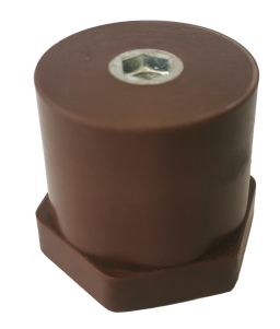
Low-voltage support insulators
OK/D 60*
Dimensions and characteristics
| Type | Dimensions (mm) | Um (V) | F (kN) | Packaging (pcs.) | ||||
|---|---|---|---|---|---|---|---|---|
| H | SW | D1 | A | M | ||||
| OK/D 6040 - M10 | 40 | 60 | 60 | 11 | M10 | 1500 | 7 | 12 |
| OK/D 6040 - M12 | 40 | 60 | 60 | 11 | M12 | 1500 | 7 | 12 |
| OK/D 6040 - M16 | 40 | 60 | 60 | 12 | M16 | 1500 | 7 | 12 |
| OK/D 6060 - M10 | 60 | 60 | 60 | 18 | M10 | 3000 | 5 | 10 |
| OK/D 6060 - M12 | 60 | 60 | 60 | 18 | M12 | 3000 | 5 | 10 |
| OK/D 6060 - M16 | 60 | 60 | 60 | 19 | M16 | 3000 | 5 | 10 |
| OK/D 6080 - M10 | 80 | 60 | 60 | 19 | M10 | 5000 | 9 | 8 |
| OK/D 6080 - M12 | 80 | 60 | 60 | 19 | M12 | 5000 | 9 | 8 |
| OK/D 6080 - M16 | 80 | 60 | 60 | 23 | M16 | 5000 | 9 | 8 |
| OK/D 60100 - M10 | 100 | 60 | 60 | 19 | M10 | 8000 | 15 | 5 |
| OK/D 60100 - M12 | 100 | 60 | 60 | 19 | M12 | 8000 | 15 | 5 |
| OK/D 60100 - M16 | 100 | 60 | 60 | 23 | M16 | 8000 | 15 | 5 |
| Technical data | OK/D 60* |
|---|---|
| Colour | Brown |
| Standard | IEC 60273:1990; IEC 60660:1999 |
| Mounting | Indoor |
| Temperature resistance (°C) | -40°C to +125°C |
| Type of basic insulation | Epoxy resin |
NOTE: OK/D 60* type insulators have excellent electrical and mechanical characteristics and can be used in extreme operating conditions such as high ambient temperatures, as well as when in contact with corrosive substances and vibration. The hexagon on the bottom is provided for a wrench, for easier mounting and fixing of the insulator. OK/D 60* type insulators are made of epoxy resin, which contributes to environmental and human health protection compared to similar materials such as glass-fibre-reinforced polyester.

Low-voltage support insulator
IPA-1
Technical characteristics
| Technical data | IPA-1 |
|---|---|
| Rated system voltage (kV) | 0,72 |
| Highest voltage for equipment (r.m.s.) (kV) | 1 |
| Breaking force (kN) | 3,75 |
| Colour | Brown |
| Standard | IEC 60273:1990; IEC 60660:1999 |
| Mounting | Indoor |
| Temperature resistance (°C) | -40°C to +125°C |
| Type of basic insulation | Epoxy resin |
| Weight (kg) | 0,2 |
NOTE: These epoxy resin support insulators can be used for all indoor applications; their cylindrical shape gives them strength, with a suitable creepage distance and number of sheds.
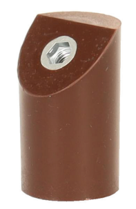
Support insulators for indoor mounting up to 1,2 kV
IP-1K
Technical characteristics
| Technical data | IP-1K |
|---|---|
| Rated system voltage (kV) | 1 |
| Highest voltage for equipment (r.m.s.) (kV) | 1,2 |
| Test voltage 50 Hz, 1 min. (kV) | 6 |
| Weight (kg) | 0,094 |
| Applicable standards | SRPS EN 60660:1999 |
| Breaking force (kN) | 2 |
| Mounting | Indoor |
| Temperature resistance | -40°C to +125°C |
| Installation area | Any area, including tropical |
| Insulation temperature class | B |
| Type of basic insulation | Epoxy resin |
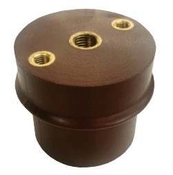
Support insulators for indoor mounting
IPC-1, IPC-1s
Dimensions
| Insulator type | Dimensions (mm) | |
|---|---|---|
| H | L | |
| IPC-1 | 80 | 45 |
| IPC-1s | 65 | 30 |
Technical characteristics
| Technical data | IPC-1s | IPC-1 |
|---|---|---|
| Rated system voltage (kV) | 0,72 | 1 |
| Highest voltage for equipment (r.m.s.) (kV) | 0,8 | 1,2 |
| Test voltage (kV) | 6 | 6 |
| Weight (kg) | 0,53 | 0,67 |
| Breaking force (kN) | 12,5 | |
| Applicable standards | SRPS EN 60664-1 | |
| Mounting | Indoor | |
| Temperature resistance | -40°C to +125°C | |
| Type of basic insulation | Epoxy resin | |
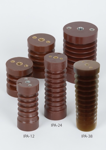
Medium-voltage support insulators for indoor mounting
Voltage: from 3.6 kV to 38 kV | Mounting: Indoor | Insulation: Epoxy resin
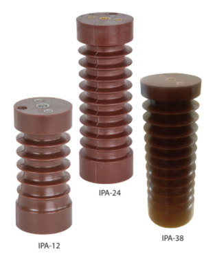
Medium-voltage support insulators
IPA-*
| TECHNICAL DATA | IPA-3,6 | IPA-7,2 | IPA-12 | IPA-24 | IPA-38 | IPA-38d |
|---|---|---|---|---|---|---|
| Rated system voltage (kV) | 3 | 6 | 10 | 20 | 35 | 35 |
| Highest voltage for equipment (r.m.s.) (kV) | 3,6 | 7,2 | 12 | 24 | 38 | 38 |
| Test voltage, 50 Hz, 1 min. (kV) | 10 | 20 | 28 | 50 | 70 | 70 |
| Test voltage 1,2/50 µs (kV) | 40 | 60 | 75 | 95 | 170 | 170 |
| Weight (kg) | ~0,32 | ~0,44 | ~0,57 | ~1,16 | ~2,09 | ~2,50 |
| Breaking force (kN) | 3,75 | |||||
| Creepage distance (mm) | 61 | 160 | 205 | 365 | 490 | 575 |
| Number of sheds | 2 | 3 | 5 | 9 | 10 | 12 |
| Applicable standards | SRPS EN 60660, SRPS EN 60060-1, IEC 60273 | |||||
| Mounting | Indoor | |||||
| Temperature resistance | -40°C to +125°C | |||||
| Altitude | Not limited | |||||
| Type of basic insulation | Epoxy resin | |||||
Dimensions (mm)
| Insulator type | H | ØD | d1 | d2 | d3 | b | t1 | t2 | t3 | t4 | a | k | l | m |
|---|---|---|---|---|---|---|---|---|---|---|---|---|---|---|
| IPA-3,6 | 60 | 60 | M10 | M10 | M6 | 36 | 12 | 12 | 9 | 2 | 35 | 7 | 8 | 8 |
| IPA-3,6-1 | 60 | 60 | M12 | M12 | M6 | 36 | 12 | 12 | 9 | 2 | 35 | 7 | 8 | 8 |
| IPA-7,2 | 95 | 60 | M16 | M10 | M6 | 36 | 22 | 17 | 6 | 8 | 42 | 7 | 8 | 8 |
| IPA-12 | 130 | 56 | M16 | M10 | M6 | 36 | 24 | 15 | 9 | 9 | 38 | 7 | 8 | 8 |
| IPA-12-1 | 130 | 60 | M16 | M10 | M6 | 36 | 24 | 15 | 9 | 9 | 38 | 7 | 8 | 8 |
| IPA-12-2 | 130 | 68 | M16 | M10 | M6 | 36 | 24 | 15 | 9 | 9 | 38 | 7 | 8 | 8 |
| IPA-24 | 210 | 65 | M16 | M10 | M6 | 36 | 24 | 15 | 9 | 15 | 45 | 7 | 8 | 8 |
| IPA-24-1 | 210 | 70 | M16 | M10 | M6 | 36 | 24 | 15 | 9 | 15 | 45 | 7 | 8 | 8 |
| IPA-24-2 | 210 | 75 | M16 | M10 | M6 | 36 | 24 | 15 | 9 | 20 | 45 | 7 | 8 | 8 |
| IPA-38 | 300 | 79 | M16 | M10 | M6 | 36 | 24 | 15 | 9 | 20 | 45 | 7 | 8 | 8 |
| IPA-38-1 | 300 | 82 | M16 | M10 | M6 | 36 | 24 | 15 | 9 | 20 | 45 | 7 | 8 | 8 |
| IPA-38d | 350 | 82 | M16 | M10 | M6 | 36 | 24 | 15 | 9 | 20 | 45 | 7 | 8 | 10 |
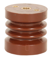
Medium-voltage support insulators
IPB-*
| TECHNICAL DATA | IPB-3,6 | IPB-12 | IPB-24 | IPB-24-1 | IPB-38 | IPB-38-1 |
|---|---|---|---|---|---|---|
| Rated system voltage (kV) | 3 | 10 | 20 | 20 | 35 | 35 |
| Highest voltage for equipment (r.m.s.) (kV) | 3,6 | 12 | 24 | 24 | 38 | 38 |
| Test voltage, 50 Hz, 1 min. (kV) | 10 | 28 | 50 | 50 | 70 | 70 |
| Test voltage 1,2/50 µs (kV) | 40 | 75 | 95 | 95 | 145 | 170 |
| Weight (kg) | ~0,62 | ~0,82 | ~1,97 | ~2,11 | ~2,99 | ~3,24 |
| Breaking force (kN) | 7,5 | |||||
| Number of sheds | 1 | 5 | 8 | 5 | 11 | 8 |
| Applicable standards | SRPS EN 60660, SRPS EN 60060-1 | |||||
| Mounting | Indoor | |||||
| Temperature resistance | -40°C to +125°C | |||||
| Altitude | Not limited | |||||
| Type of basic insulation | Epoxy resin | |||||
Dimensions (mm)
| Insulator type | H | ØD | d1 | d2 | d3 | b | t1 | t2 | t3 | t4 | a | k | l | m |
|---|---|---|---|---|---|---|---|---|---|---|---|---|---|---|
| IPB-3,6 | 65 | 82 | M16 | M16 | M10 | 46 | 20 | 20 | 12 | / | 35 | 7 | 8 | 8 |
| IPB-3,6-1 | 87 | 75 | M16 | M16 | M10 | 46 | 24 | 24 | 12 | / | 35 | 7 | 8 | 8 |
| IPB-3,6-2 | 78 | 82 | M16 | M16 | M10 | 46 | 24 | 24 | 14 | / | 42 | 7 | 8 | 8 |
| IPB-12 | 130 | 76 | M20 | M16 | M10 | 46 | 26 | 24 | 12 | 15 | 38 | 7 | 8 | 8 |
| IPB-12-1 | 130 | 82 | M20 | M16 | M10 | 46 | 30 | 24 | 12 | 12 | 38 | 7 | 8 | 8 |
| IPB-24 | 210 | 80 | M20 | M16 | M10 | 46 | 30 | 24 | 12 | 18 | 38 | 7 | 8 | 8 |
| IPB-24-1 | 225 | 100 | M20 | M16 | M10 | 46 | 26 | 22 | 16 | / | 38 | 7 | 8 | 8 |
| IPB-38 | 300 | 93 | M24 | M16 | M10 | 46 | 34 | 24 | 12 | 20 | 60 | 8,5 | 10 | 8 |
| IPB-38-1 | 325 | 95 | M24 | M16 | M10 | 46 | 34 | 22 | 12 | / | 60 | 8,5 | 10 | 8 |
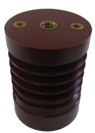
Medium-voltage support insulators
IPC-*
| TECHNICAL DATA | IPC-12 | IPC-24 | IPC-38 |
|---|---|---|---|
| Rated system voltage (kV) | 10 | 20 | 35 |
| Highest voltage for equipment (r.m.s.) (kV) | 12 | 24 | 38 |
| Test voltage, 50 Hz, 1 min. (kV) | 28 | 50 | 70 |
| Test voltage 1,2/50 µs (kV) | 75 | 125 | 170 |
| Weight (kg) | ~1,70 | ~2,40 | ~4,10 |
| Breaking force (kN) | 12,5 | ||
| Number of sheds | 5 | 8 | 11 |
| Applicable standards | SRPS EN 60660, SRPS EN 60060-1, IEC 60273 | ||
| Mounting | Indoor | ||
| Temperature resistance | -40°C to +125°C | ||
| Type of basic insulation | Epoxy resin | ||
Dimensions (mm)
| Insulator type | H | ØD | d1 | d2 | d3 | b | t1 | t2 | t3 | t4 | a | k | l | m |
|---|---|---|---|---|---|---|---|---|---|---|---|---|---|---|
| IPC-12 | 130 | 100 | M20 | M16 | M10 | 66 | 30 | 24 | 12 | 18 | 55 | 7 | 8 | 8 |
| IPC-24 | 210 | 105 | M24 | M16 | M10 | 66 | 34 | 24 | 12 | 24 | 50 | 7 | 8 | 8 |
| IPC-38 | 300 | 105 | M30 | M16 | M10 | 66 | 40 | 24 | 12 | 20 | 70 | 8,5 | 10 | 8 |
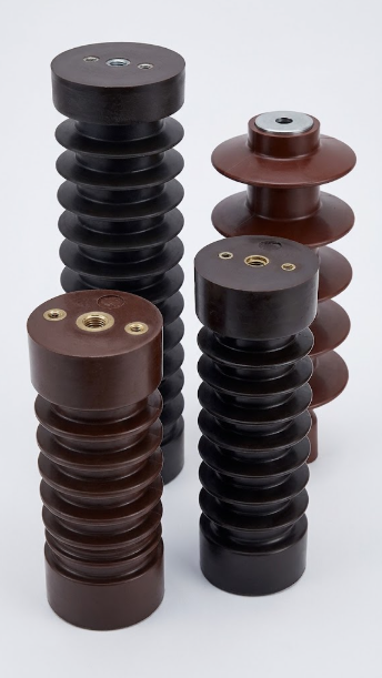
Medium-voltage support insulators with voltage indicator
Voltage: from 6 kV to 38 kV | Mounting: Indoor | Insulation: Epoxy resin
Used to detect the presence of voltage on phase conductors.
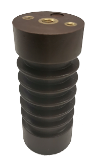
Medium-voltage support insulators with voltage indicator
IPA-12C, IPA-24C, IPA-38C
| TECHNICAL DATA | IPA-12C | IPA-24C | IPA-38C |
|---|---|---|---|
| Rated system voltage (kV) | 6; 10 | 15; 20 | 35 |
| Highest voltage for equipment (r.m.s.) (kV) | 7,2; 12 | 17,5; 24 | 38 |
| Test voltage, 50 Hz, 1 min. (kV) | 20; 28 | 50 | 70 |
| Weight (kg) | ~0,4 | ~1,0 | ~2,0 |
| Breaking force (kN) | 3,75 | ||
| Applicable standards | SRPS EN 60660, IEC 61243-5, IEC 60273 | ||
| Mounting | Indoor | ||
| Temperature resistance | -40°C to +125°C | ||
| Type of basic insulation | Epoxy resin | ||
Dimensions (mm)
| Insulator type | H | ØD | d1 | d2 | d3 | d4 | e | b | t1 | t2 | t3 | t4 | t5 |
|---|---|---|---|---|---|---|---|---|---|---|---|---|---|
| IPA-12C | 130 | 56 | M16 | M10 | M6 | M6 | 20 | 36 | 24 | 15 | 9 | 10 | 10 |
| IPA-12-1C | 130 | 60 | M16 | M10 | M6 | M6 | 20 | 36 | 24 | 15 | 9 | 10 | 10 |
| IPA-12-2C | 130 | 68 | M16 | M10 | M6 | M6 | 20 | 36 | 24 | 15 | 9 | 10 | 10 |
| IPA-24C | 210 | 65 | M16 | M10 | M6 | M6 | 25 | 36 | 24 | 15 | 9 | 15 | 9 |
| IPA-24-1C | 210 | 70 | M16 | M10 | M6 | M6 | 25 | 36 | 24 | 15 | 9 | 15 | 9 |
| IPA-24-2C | 210 | 75 | M16 | M10 | M6 | M6 | 25 | 36 | 24 | 15 | 9 | 20 | 9 |
| IPA-38C | 300 | 79 | M16 | M10 | M6 | M6 | 25 | 36 | 24 | 15 | 9 | 20 | 9 |
| IPA-38-1C | 300 | 82 | M16 | M10 | M6 | M6 | 25 | 36 | 24 | 15 | 9 | 20 | 9 |
NOTE: These insulators are used to detect the presence of voltage on phase conductors. The basic operating principle is based on capacitive division of the phase voltage. Voltage indicators are used with a capacitive coupled voltage-indicating system. To order these insulators, the following information is required: the type of voltage detection system (HR or LRM system); the rated (operating) voltage; the capacitance of the indicator (insulator).
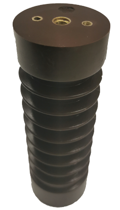
Medium-voltage support insulators with voltage indicator
IPB-12C, IPB-24C, IPB-38C
| TECHNICAL DATA | IPB-12C | IPB-24C | IPB-38C |
|---|---|---|---|
| Rated system voltage (kV) | 6; 10 | 15; 20 | 35 |
| Highest voltage for equipment (r.m.s.) (kV) | 7,2; 12 | 17,5; 24 | 38 |
| Test voltage, 50 Hz, 1 min. (kV) | 20; 28 | 50 | 70 |
| Weight (kg) | ~0,8 | ~1,0 | ~2,0 |
| Breaking force (kN) | 7,5 | ||
| Applicable standards | SRPS EN 60660, IEC 61243-5, IEC 60273 | ||
| Mounting | Indoor | ||
| Temperature resistance | -40°C to +125°C | ||
| Type of basic insulation | Epoxy resin | ||
Dimensions (mm)
| Insulator type | H | ØD | d1 | d2 | d3 | d4 | e | b | t1 | t2 | t3 | t4 | t5 |
|---|---|---|---|---|---|---|---|---|---|---|---|---|---|
| IPB-12C | 130 | 76 | M20 | M16 | M10 | M6 | 20 | 46 | 26 | 24 | 12 | 15 | 15 |
| IPB-12-1C | 130 | 82 | M20 | M16 | M10 | M6 | 20 | 46 | 30 | 24 | 12 | 12 | 12 |
| IPB-24C | 210 | 80 | M20 | M16 | M10 | M6 | 25 | 46 | 30 | 24 | 12 | 18 | 12 |
| IPB-38C | 300 | 93 | M24 | M16 | M10 | M6 | 25 | 46 | 34 | 24 | 12 | 20 | 12 |
NOTE: These insulators are used to detect the presence of voltage on phase conductors. The basic operating principle is based on capacitive division of the phase voltage. Voltage indicators are used with a capacitive coupled voltage-indicating system. To order these insulators, the following information is required: the type of voltage detection system (HR or LRM system); the rated (operating) voltage; the capacitance of the indicator (insulator).
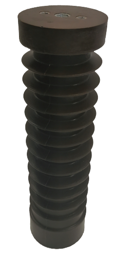
Medium-voltage support insulators with voltage indicator
IPC-12C, IPC-24C, IPC-38C
| TECHNICAL DATA | IPC-12C | IPC-24C | IPC-38C |
|---|---|---|---|
| Rated system voltage (kV) | 6; 10 | 15; 20 | 35 |
| Highest voltage for equipment (r.m.s.) (kV) | 7,2; 12 | 17,5; 24 | 38 |
| Test voltage, 50 Hz, 1 min. (kV) | 20; 28 | 50 | 70 |
| Weight (kg) | ~0,9 | ~2,4 | ~4,1 |
| Breaking force (kN) | 12,5 | ||
| Applicable standards | SRPS EN 60660, IEC 61243-5, IEC 60273 | ||
| Mounting | Indoor | ||
| Temperature resistance | -40°C to +125°C | ||
| Type of basic insulation | Epoxy resin | ||
Dimensions (mm)
| Insulator type | H | ØD | d1 | d2 | d3 | d4 | e | b | t1 | t2 | t3 | t4 | t5 |
|---|---|---|---|---|---|---|---|---|---|---|---|---|---|
| IPC-12C | 130 | 100 | M20 | M16 | M10 | M6 | 20 | 66 | 30 | 24 | 12 | 18 | 18 |
| IPC-24C | 210 | 105 | M24 | M16 | M10 | M6 | 25 | 66 | 34 | 24 | 12 | 24 | 12 |
| IPC-38C | 300 | 105 | M30 | M16 | M10 | M6 | 25 | 66 | 40 | 24 | 12 | 20 | 12 |
NOTE: These insulators are used to detect the presence of voltage on phase conductors. The basic operating principle is based on capacitive division of the phase voltage. Voltage indicators are used with a capacitive coupled voltage-indicating system. To order these insulators, the following information is required: the type of voltage detection system (HR or LRM system); the rated (operating) voltage; the capacitance of the indicator (insulator).
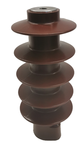
Medium-voltage capacitive support insulator
CSI 24-I, CSI 24-II
| TECHNICAL DATA | CSI 24-1 | CSI 24-2 |
|---|---|---|
| Rated system voltage (kV) | 15; 20 | |
| Highest voltage for equipment (r.m.s.) (kV) | 17,5; 24 | |
| Breaking force (kN) | 1,5 | |
| Colour | Brown | |
| Standard | IEC 60273:1990; IEC 60660:1999; IEC 61243-5 | |
| Mounting | Indoor | |
| Temperature resistance | -40°C to +125°C | |
| Type of basic insulation | Epoxy resin | |
| Weight (kg) | 1,1 | 0,9 |
NOTE: Medium-voltage capacitive support insulator, 24 kV. These insulators are used to detect the presence of voltage on phase conductors. The basic operating principle is based on capacitive division of the phase voltage. Voltage indicators are used with a capacitive coupled voltage-indicating system. To order these insulators, the following information is required: the type of voltage detection system (HR or LRM system); the rated (operating) voltage; the capacitance of the indicator (insulator).
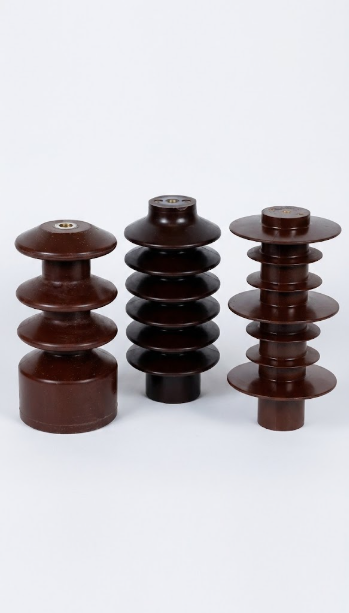
Medium-voltage support insulators for outdoor mounting
Voltage: from 6 kV to 38 kV | Mounting: Outdoor | Insulation: Epoxy resin
Designed for operation in outdoor conditions with high levels of pollution and atmospheric contamination.
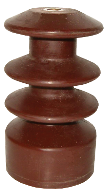
Medium-voltage support insulators for outdoor mounting
IPAS-7,2, IPAS-24
| TECHNICAL DATA | IPAS-7,2 | IPAS-24 |
|---|---|---|
| Rated system voltage (kV) | 6 | 15; 20 |
| Highest voltage for equipment (r.m.s.) (kV) | 7,2 | 17,5; 24 |
| Test voltage, 50 Hz, 1 min. (kV) | 20 | 38; 50 |
| Test voltage 1,2/50 µs (kV) | 60 | 95; 125 |
| Weight (kg) | 0,55 | 2,0 |
| Breaking force (kN) | 3,75 | 12,5 |
| Number of sheds | 3 | 6 |
| Creepage distance (mm) | 230 | 617 |
| Applicable standards | SRPS EN 60660, SRPS EN 60060-1 | |
| Mounting | Outdoor | |
| Temperature resistance | -40°C to +125°C | |
| Type of basic insulation | Epoxy resin | |
NOTE: These epoxy resin support insulators can be used for all outdoor applications. Their cylindrical shape gives them strength, with a suitable creepage distance and number of sheds.
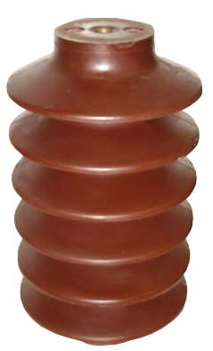
Medium-voltage support insulators for outdoor mounting
IPBS-12, IPBS-24, IPBS-38
| TECHNICAL DATA | IPBS-12 | IPBS-24 | IPBS-38 |
|---|---|---|---|
| Rated system voltage (kV) | 10 | 20 | 35 |
| Highest voltage for equipment (r.m.s.) (kV) | 12 | 24 | 38 |
| Test voltage, 50 Hz, 1 min. (kV) | 28 | 50 | 70 |
| Test voltage 1,2/50 µs (kV) | 75 | 125 | 170 |
| Weight (kg) | 3,20 | 4,83 | 5,70 |
| Breaking force (kN) | 7,5 | ||
| Creepage distance (mm) | 350 | 645 | 778 |
| Number of sheds | 4 | 6 | 8 |
| Applicable standards | SRPS EN 60660, SRPS EN 60060-1 | ||
| Mounting | Outdoor | ||
| Temperature resistance | -40°C to +125°C | ||
| Type of basic insulation | Epoxy resin | ||
Dimensions (mm)
| Insulator type | H | Ød | ØD | ØD1 | b | a | α |
|---|---|---|---|---|---|---|---|
| IPBS-12 | 210 | 70 | 120 | 115 | 43 | 3 | 30° |
| IPBS-24 | 280 | 80 | 160 | 160 | 40 | 5 | 26° |
| IPBS-38 (in the catalogue: IPBS-36) | 360 | 90 | 160 | 160 | 40 | 7 | 26° |
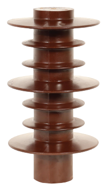
Medium-voltage support insulators for outdoor mounting
C4-75, C4-125, C4-170, C16-75
| TECHNICAL DATA | C4-75 | C4-125 | C4-170 | C16-75 |
|---|---|---|---|---|
| Rated system voltage (kV) | 10 | 20 | 35 | 10 |
| Highest voltage for equipment (r.m.s.) (kV) | 12 | 24 | 38 | 12 |
| Test voltage, 50 Hz, 1 min. (kV) | 28 | 50 | 70 | 28 |
| Test voltage 1,2/50 µs (kV) | 75 | 125 | 170 | 75 |
| Weight (kg) | 1,78 | 2,82 | 5,17 | 3,60 |
| Breaking force (kN) | 4 | 4 | 4 | 12,5 |
| Creepage distance (mm) | 485 | 670 | 890 | 415 |
| Number of sheds | 5 | 7 | 10 | 5 |
| Applicable standards | SRPS EN 60660, SRPS EN 60060-1 | |||
| Mounting | Outdoor | |||
| Temperature resistance | -40°C to +125°C | |||
| Altitude | Not limited | |||
| Type of basic insulation | Epoxy resin | |||
Dimensions (mm)
| Insulator type | H | ØD | ØD1 | ØD2 | E | K |
|---|---|---|---|---|---|---|
| C4-75 | 200 | 150 | 60 | 100 | 36 | 38 |
| C4-125 | 300 | 160 | 70 | 110 | 50 | 42 |
| C4-170 | 400 | 170 | 80 | 120 | 46 | 46 |
| C16-75 | 180 | 160 | 100 | / | 60 | / |