Easy-to-install pole-mounted power substation
Technical description
According to the recommendations of EPS (Electric Power Industry of Serbia), conditions have been determined for the construction of pole-mounted substations in 10 and 20 kV networks. The construction of substations is allowed once energy permit is obtained with respect to the location of installation, and when all technical conditions for the construction of pole-mounted substations from 50 to 400 kVA are met.
One of the technical conditions is the installation of new supporting poles for the pole-mounted substation, as well as the installation of a tension pole before the supporting pole of the substation. In order to avoid these conditions, especially in requests for smaller substations, FMT comes forward with a solution for building the substation on 10 and 20 kV line poles for a rated power up to 63 kVA.
Until now, the construction of pole-mounted power substations was possible only with three-phase transformers and three-pole line disconnectors with fuses and surge arresters, and all that equipment was placed on one side of the substation pole. Equipment completed in this way had a lot of weight and thus overloaded the pole, so that supporting poles with increased load-bearing capacity had to be specially designed. In addition to those poles, due to the tension force from the entire structure of the substation, and according to the recommendations of EPS, a tension pole also had to be installed before the substation pole.
To avoid this, the solution offered by FMT is placing the substation equipment for each phase individually at 120° looking from above, so that the lateral tension forces from the equipment are cancelled out. The equipment is designed and built in such a way that the single-phase equipment is coupled into a three-phase system on-site, and the entire load from the equipment results in a force attacking the bottom of the pole, i.e., the foundation.
Since FMT has dry power transformers in its production program, as well as all measuring transformers for billing metering in the open - for outdoor mounting, the idea for creating such a project was born, with the aim of offering a solution to interested power distribution companies and investors that would suit both parties.
The solution offered by this project is the COMPLETE EQUIPMENT FOR SUBSTATION CONSTRUCTION for outdoor mounting, which can be placed, first of all, on line poles of 9, 11, and 12 m in height.
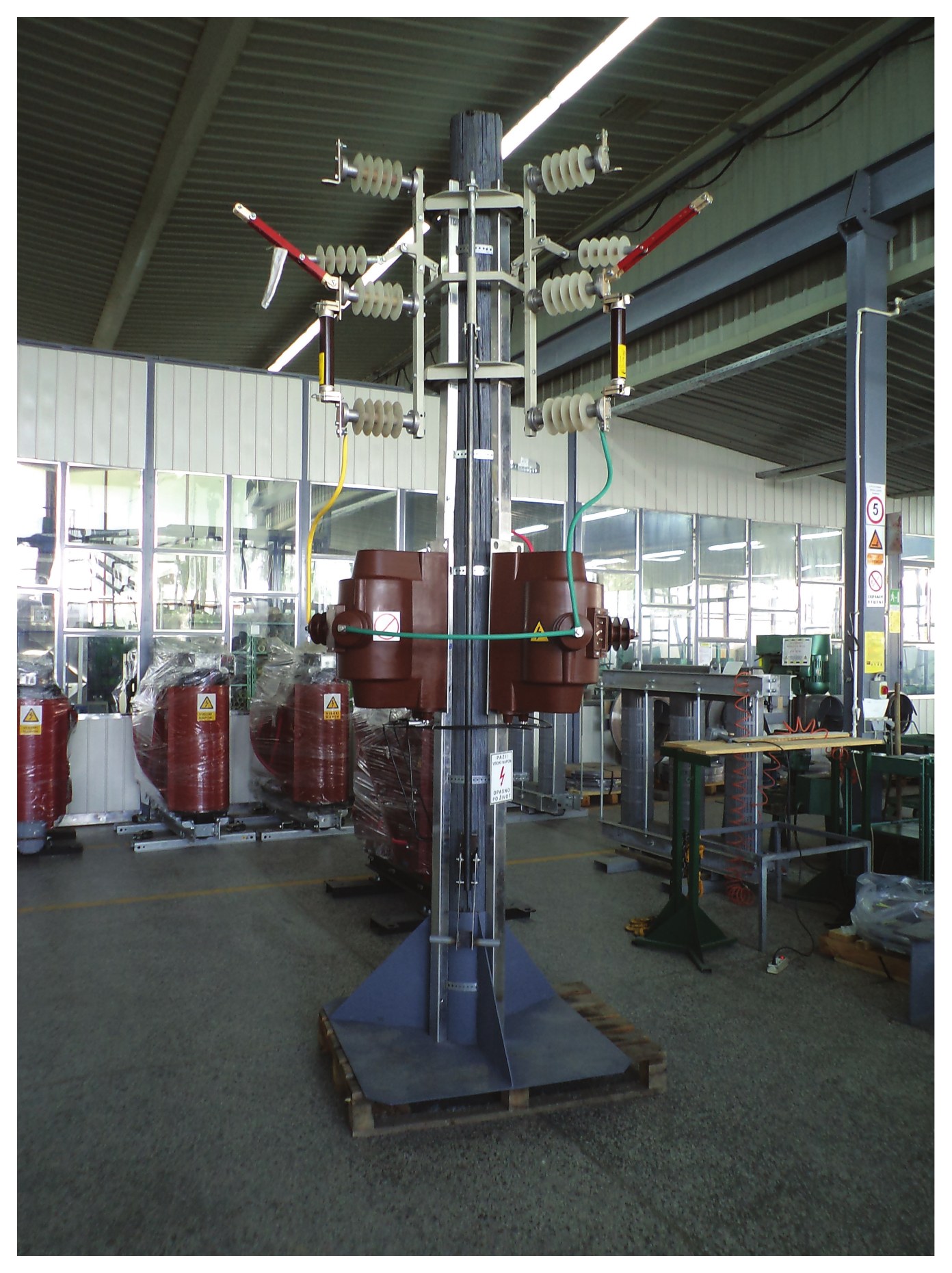
Easy-to-install pole-mounted power substation
STS-10, STS-12, STS-15, STS-30, STS-50, STS-63
This project provides for the following types of EASY-TO-INSTALL POLE-MOUNTED POWER SUBSTATIONS:
| Item No. | Type of the substation | Voltage regulation | Power transformer |
|---|---|---|---|
| 1 | STS - 10; 10 kVA, 10/0.42±5% kV/kV | From the secondary side | DTES - 3.3 |
| 2 | STS - 12; 12 kVA, 10/0.42±5% kV/kV | DTES - 4 | |
| 3 | STS - 15; 15 kVA, 10/0.42±5% kV/kV | DTES - 5 | |
| 4 | STS - 30; 30 kVA, 10/0.42±5% kV/kV | From the primary side | DTES - 10 |
| 5 | STS - 50; 50 kVA, 10/0.42±5% kV/kV | DTES - 17 | |
| 6 | STS - 63; 63 kVA, 10/0.42±5% kV/kV | DTES - 21 |
Click a power transformer type to go to its characteristics and sketches at the bottom of the page.
This project offers two variant solutions:
- Pole-mounted power substation with low-voltage metering, and
- Pole-mounted power substation with indirect medium-voltage metering.
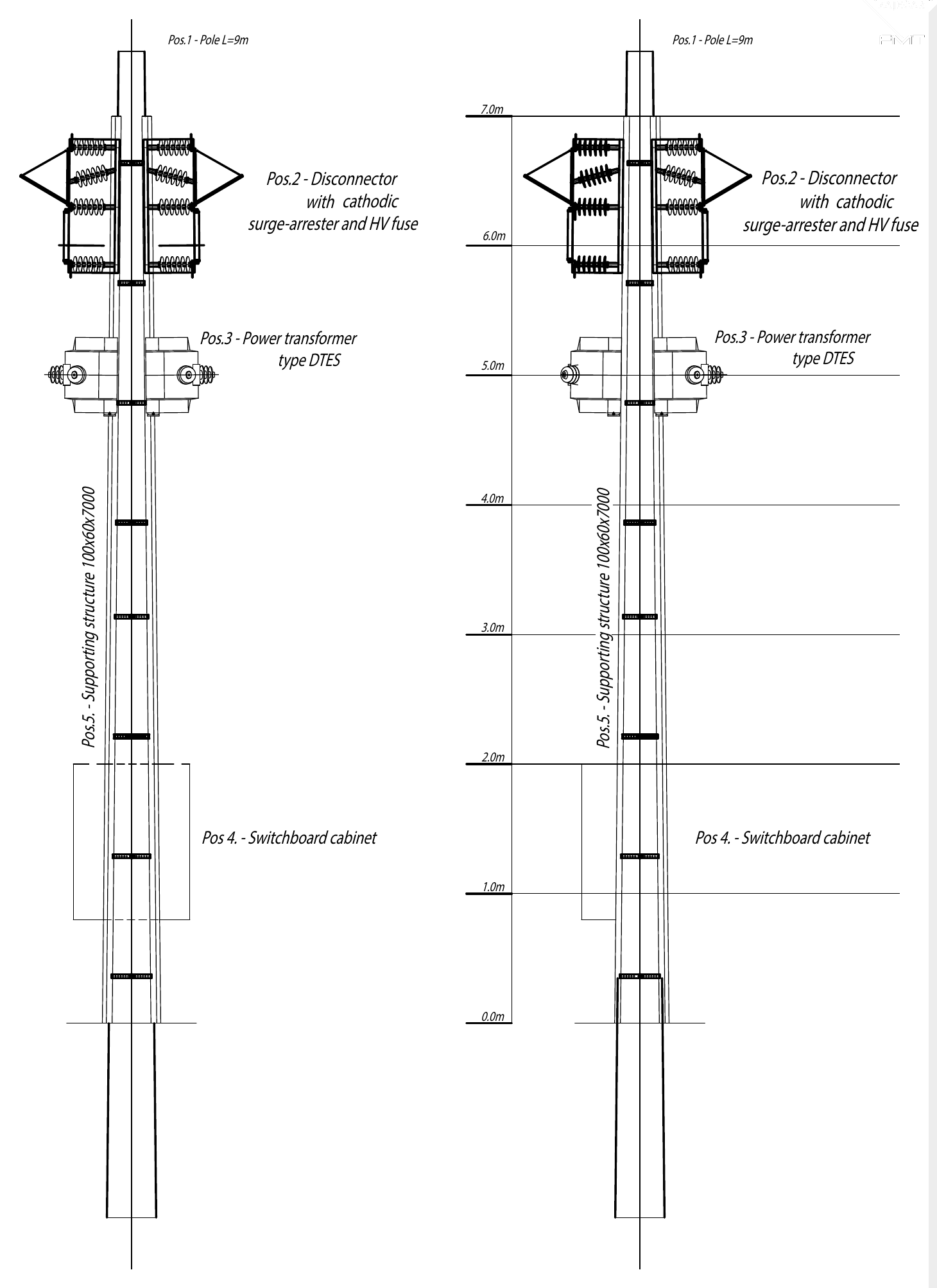
This type of pole-mounted substation is designed for individual phase element installation on concrete line poles, with metering on the low-voltage side.
The pole-mounted substation consists of:
- a supporting structure, 7 m;
- three single-pole disconnectors coupled into a three-phase system at 120°, with HV HRC fuse holders and surge arresters;
- three two-phase power transformers coupled into a three-phase system.
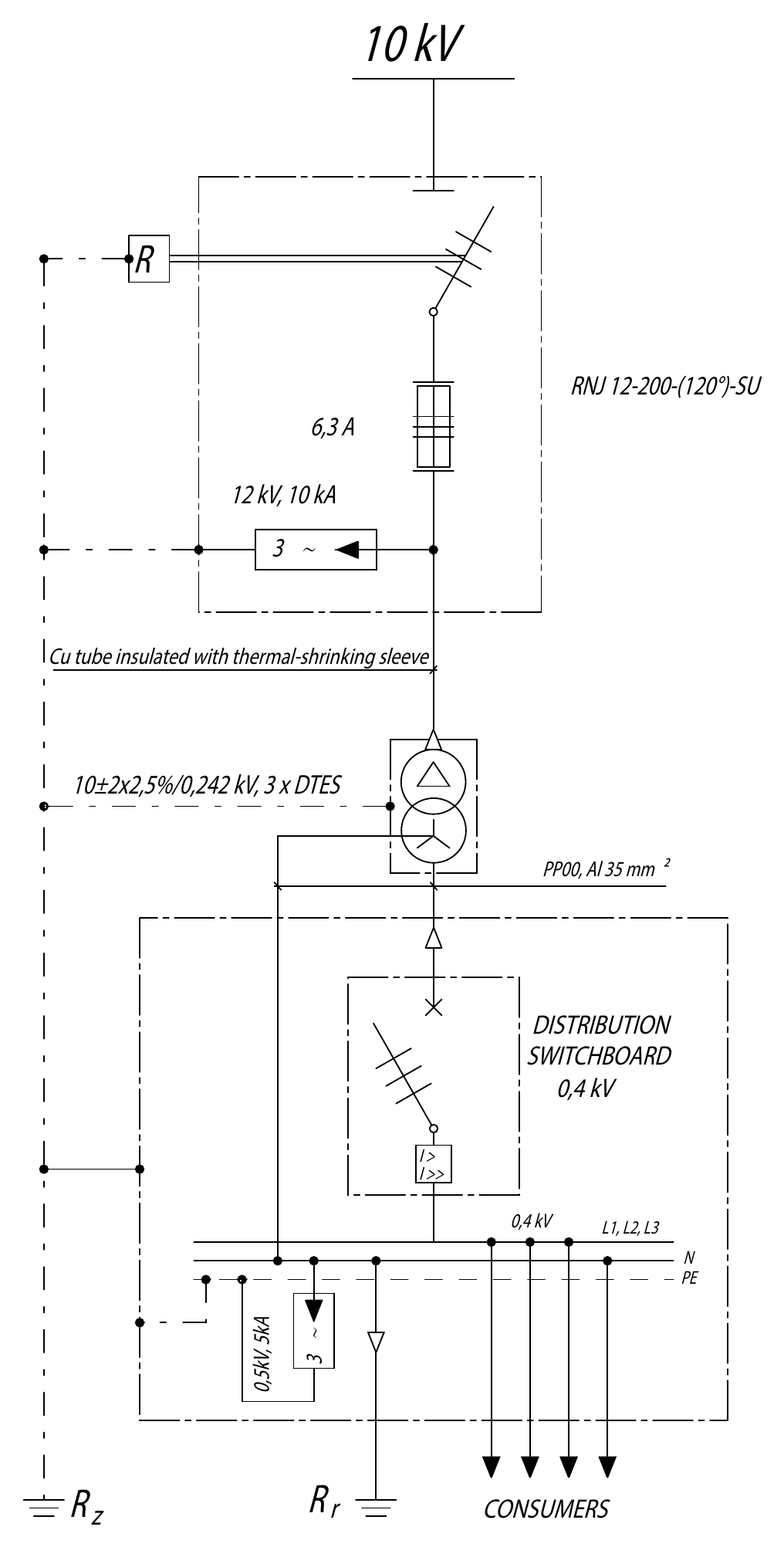
Protection of the power transformer against short-circuit current from the primary side is executed via HV HRC fuses, and protection against atmospheric overvoltages is executed by surge arresters located on the disconnector itself.
Protection against short-circuit current from the secondary side is an automatic molded case circuit breaker (MCCB) 100 A; 500 V, and against atmospheric overvoltages there are low-voltage surge arresters 500 V; 5 kA.
The automatic molded case circuit breaker and low-voltage surge arresters are located in the low-voltage distribution cabinet.
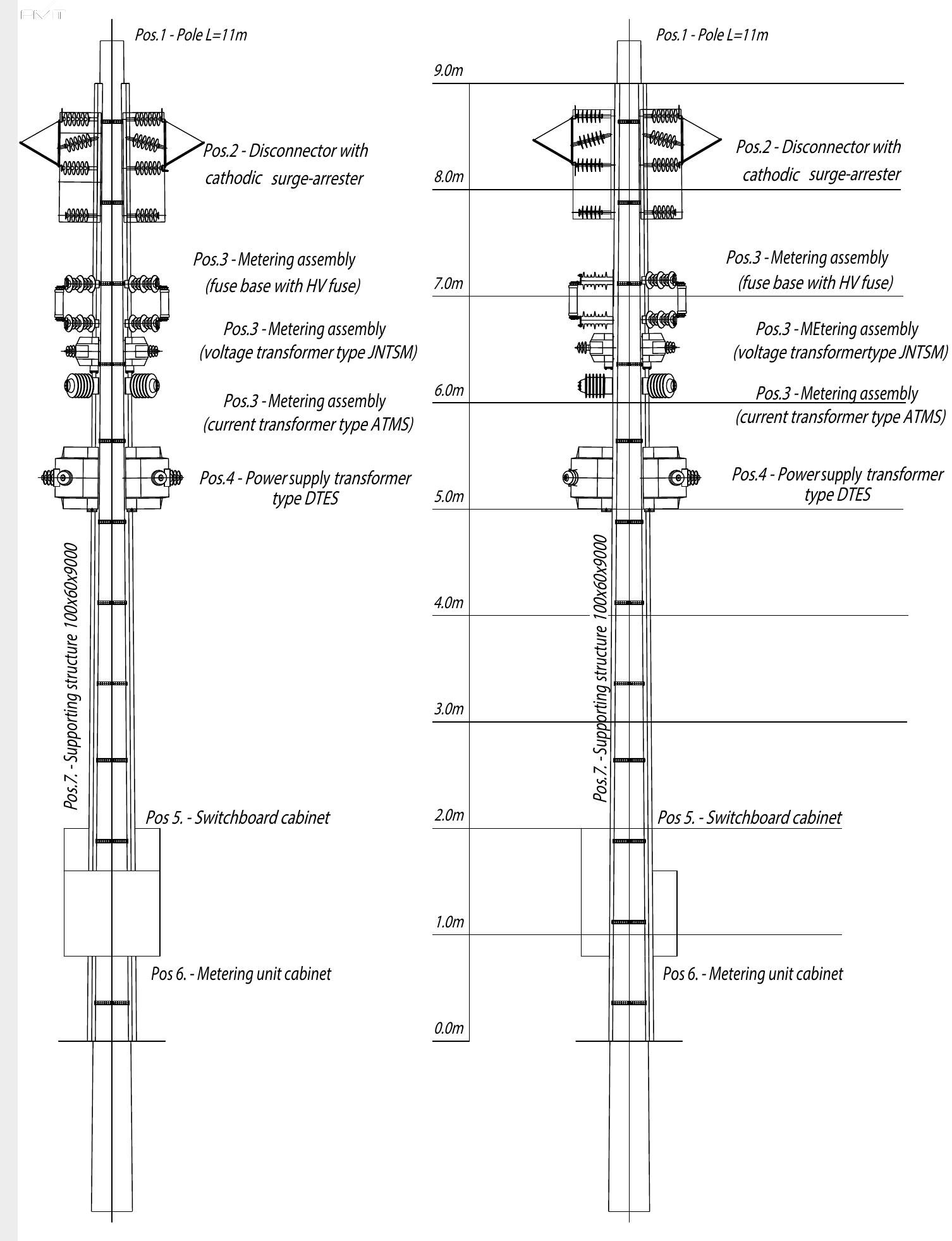
This type of pole-mounted substation is designed for individual phase element installation on concrete line poles, with indirect metering on the medium-voltage side.
The pole-mounted substation consists of:
- a supporting structure, 9 m;
- three single-pole disconnectors coupled into a three-phase system at 120°, with surge arresters;
- three two-phase power transformers coupled into a three-phase system;
- three single-pole HV fuse holders with HV HRC fuses;
- three single-pole insulated voltage measuring transformers 10√3//0,1√3 kV/kV;
- three current measuring transformers of insulation level 20 kV;
- a complete indirect three-system metering unit in a separate cabinet on the same pole.
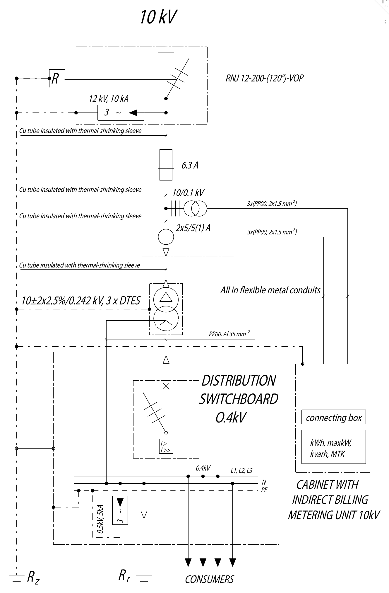
In the direction of power flow, the metering assembly on the 10 kV side connects directly behind (below) the switch-disconnector with surge arresters, and in front of the power transformer, as shown in the attached drawings.
The metering assembly on the 10 kV side consists of: an HV fuse holder, voltage measuring transformers, and a current measuring transformer. All these parts are mounted individually and very quickly via pins and cotter pins.
Protection of all elements of the assembly (and the power transformer) is primarily via HV HRC fuses (6.3 A or 10 A), and secondarily (on the 100/√3 V side), the metering group is protected via 3 automatic circuit breakers 6 A, in the connection box.
Special protection (against overload and short circuit) of the voltage measuring transformers is not provided, which is in accordance with the modern technical approach, because such (special) protection has been abandoned by (almost) all world equipment manufacturers.
The reason should be sought in the facts that special HV HRC fuses for this purpose require an increased equipment size and that failures on voltage measuring transformers are very rare. Even if they do happen - due to the circumstance that the primary current values are very small (below 1 mA), and the primary windings of the voltage measuring transformer are of a very small cross-section - the eventual failure is interrupted locally without consequences.
All elements of the substation are placed in one line, and the connections between all electrical devices and the power transformer are executed with single-core cables XHE 49A, 1x35 mm² (from a 10 kV aerial bundled cable - ABC), with cable terminations for outdoor mounting on both sides or copper tubes with a heat-shrinkable sleeve.
Elements
Equipment of the easy-to-install pole-mounted power substation, in the order in which it is described in the project.
The supporting structure is metal, composed of assembly perforated “U” profiles of dimensions 100x60x3000 mm assembled so as to achieve the required height. These profiles are placed on the round stem of a concrete pole at an angle of 120°, specifically 3 profiles on each side. These profiles are fastened at the joint locations with clamps so that 3 profiles placed in a single line give a height of 7 m or 9 m. These consoles have openings in specific places for fitting individual devices of the substation, primarily power transformers, voltage and current measuring transformers, as well as HV fuse holders.
The supporting structure connects to special general-purpose consoles using 2 connectors for each of the elements, made of steel rod material.
The supporting structure and all connecting parts are made of steel sheet, which is hot-dip galvanized for corrosion protection.
The supporting structure connects to the main earth conductor of the pole at the same place as the disconnector, using the ELDS kit. For this purpose, a hole with an opening of 13 mm is provided on the upper part of the structure.
The metal supporting structure, to which the equipment is attached, has a profile cross-section greater than 100 mm².
Connected via the ELDS kit to the main earth conductor of the pole-mounted transformer substation, it is considered an integral part of the earth conductor and is used for connecting the earthing of the equipment it carries.
The applied fuse holders are mounted on apparatus post insulators of type C4-125, which are certified for an operating voltage of 20 kV.
They are intended for outdoor mounting, for vertical and horizontal placement, with a certified breaking load of 4 kN and a creepage distance of 670 mm.
The fuse clips (grips) for the HV fuses are made of hard copper, protected against corrosion by electrolytic tin plating.
Mechanical safety latches for protecting the HV fuse links from falling out are made of galvanized steel.
Dry-insulated voltage transformers of type JNT SM-12 are applied. The transformers are insulated with epoxy resin, intended for outdoor installation, for vertical and horizontal placement.
They are completely cast, obtaining a body with a smooth surface, made of one piece, whose homogeneity ensures high dielectric strength and mechanical endurance.
The voltage transformers JNT SM-12 are single-pole insulated, with one core.
The magnetic core is of the stacked type, and the windings are made of copper, executed as layered. This ensures a rational distribution of radial and axial stresses, as well as good endurance against power-frequency overvoltages and impulse overvoltages.
Transformers of type JNT SM-12 are intended for connection between phase and neutral. The transformers are also designed for operation at line voltage for a duration of 8 hours because they have a voltage factor of 1.9/8h.
They are harmonized with standards: IEC, CSA, VDE, ANSI, BS, GOST, and SRPS.
Three single-pole voltage transformers are placed independently, each on its own U profile at an angle of 120°, looking from above.
| TECHNICAL DATA | JNT SM-12 |
|---|---|
| Rated voltage for equipment (kV) | 12 |
| Rated primary voltage (kV) | 10 |
| Rated secondary voltage (V) | 100/√3 |
| Test induced withstand voltage 150Hz/40s (kV) | 28 |
| Test impulse voltage (kV) | 75 |
| Rated frequency (Hz) | 50 |
| Accuracy class | 0,5 |
| Rated power (VA) | 50 |
| Valid standards | EN/IEC 61869-1, EN/IEC 61869-3 |
| Creepage distance (mm) | 500 |
| Mass (kg) | 26 |
| Installation | in any position |
| Operating temperature range | -55°C to +75°C |
Current transformers of type ATMS-2411 are applied. They are primary-reconnectable.
They can be installed in both vertical and horizontal positions.
| TECHNICAL DATA | ATMS-2411 |
|---|---|
| Rated voltage (kV) | 20 |
| Rated voltage for equipment (kV) | 24 |
| Test voltage 50Hz, 1min (kV) | 50 |
| Test impulse voltage 1,2/50µs (kV) | 125 |
| Rated frequency (Hz) | 50/60 |
| Rated primary current (A) | 2x5 to 2x600 |
| Rated secondary current (A) | 5 or 1 |
| Rated thermal current, 1s | Ith=(100-200)In max 20 kA |
| Rated dynamic current | Idyn=2,5Ith |
| Rated continuous thermal current | Itth=1,2In |
| Instrument security factor | FS5 |
| Rated power (VA) | 10 |
| Accuracy class | 0,5 |
| Thermal class of insulation | E/B |
| Number of cores | 1 |
| Basic insulation type | epoxy resin |
| Creepage distance (mm) | 570 |
| Mass (kg) | 16.5 |
| Valid standards | EN/IEC 61869-1, EN/IEC 61869-2 |
Dry-insulated power transformers of type DTES are applied, for the 10 kV voltage level. The transformers are insulated with epoxy resin, intended for outdoor installation, for vertical and horizontal placement.
The magnetic core is of the laminated type, and the windings are made of copper, executed as layered. This ensures a rational distribution of radial and axial stresses, as well as good endurance against power-frequency overvoltages and impulse overvoltages.
The transformers are completely cast. In this way, a body with a smooth surface is obtained, made of one piece, whose homogeneity ensures high dielectric strength and mechanical endurance.
Transformers of type DTES are intended for connection between phases, so it is possible to couple three transformers from the primary side into a delta connection, and from the secondary side into a star connection. The transformers are designed for continuous operation at line voltage.
The transformers are harmonized with the standard: EN/IEC 60076-11.
Three power transformers are galvanically connected by connectors made of copper tubes with a heat-shrinkable sleeve.
Characteristics of dry-power transformers:
- These transformers cannot catch fire, and the insulation cannot leak out;
- They are of smaller dimensions because they have special electromagnetic field absorbers;
- The insulation does not change characteristics at extreme temperatures from -30°C to +45°C;
- There is no need for maintenance;
- They do not pollute the environment;
- They are quiet during operation - they do not produce noise;
- The outer surface is smooth and rounded and does not retain dust;
- Their service life is longer under operating conditions - they are highly reliable;
- They are of smaller dimensions, and installation is easier and cheaper.
| TECHNICAL DATA | DTES-3.3 | DTES-4 | DTES-5 | DTES-10 | DTES-17 | DTES-21 |
|---|---|---|---|---|---|---|
| Rated voltage for equipment (kV) | 12 | |||||
| Rated primary voltage (kV) | 10 | |||||
| Rated secondary voltage (V) | 242 | |||||
| Power-frequency withstand voltage 50Hz, 1min (kV) | 28 | |||||
| Impulse voltage (kV) | 75 | |||||
| Rated frequency (Hz) | 50 | |||||
| Rated power (kVA) | 3.3 | 4 | 5 | 10 | 17 | 21 |
| Valid standards | EN/IEC 60076-11 | |||||
| Creepage distance (mm) | 660 | 660 | 660 | 650 | 650 | 650 |
| Mass (kg) | 65 | 71 | 78 | 145 | 165 | 185 |
| Mounting | Horizontal and vertical | |||||
| Operating temperature range | -30°C to +45°C | |||||
The base of the power transformer is designed for easy mounting. Openings of Ø30mm serve for hanging hooks, by means of which the transformer is raised to the required height with the help of a pulley block and then a pin (pin Ø16mm with beta cotter pin - 2 pcs) is simply passed through, by which the transformer is hung onto the supporting structure.
The metering of consumed electrical energy and peak (maximum reached 15-minute power in the billing period) is provided using a three-system metering unit for indirect metering, on the 10 kV side, located in a separate cabinet which is placed on the pole stem.
A multi-functional digital meter of type TMG2 (100/√3 V) is used as the metering unit, which performs in a single housing:
- Metering of consumed active electrical energy in 2 tariffs, Class 1;
- Metering of consumed reactive electrical energy in 2 tariffs, Class 3;
- Metering of the reached maximum of 15-minute active power, in 2 tariffs, Class 1;
- Reception of ripple control telegrams;
- Memorizing the maximum power state for the last 12 reading cycles.
The meter is approved for use by the Directorate of Measures and Precious Metals and accepted for use in the consumption area of EDB (Belgrade Electro-distribution).
Connection diagrams can be seen on the single-pole schemes.
The cabinet also contains:
- A metering connection box, with 3 automatic circuit breakers 6 A, with a sealed transparent cover;
- Conductors for wiring, small materials, and accessories.
The connection between the voltage measuring transformers and the metering group is established via 3 cables of 1 kV, type PP, cross-section 2x1.5 mm², and between the current measuring transformers and the metering group via 3 cables of 1 kV, type PP, cross-section 2x2.5 mm².
All cables are individually placed in flexible galvanized steel conduits, and all connection points are sealed.
The conduits are fastened to the pole with straps made of stainless material, at a distance of 1 m.
For medium-voltage connections: disconnector - HV fuse holders - voltage measuring transformers - current measuring transformers, copper tubes insulated with a heat-shrinkable sleeve are provided.
The connection between the Metering Assembly on the 10 kV side and the power transformer is also via copper tubes insulated with a heat-shrinkable sleeve.
For each phase, the copper tubes are insulated with a heat-shrinkable sleeve of the corresponding color (red, yellow, and green), so that the complete connection per phase is in the same color.
All provided equipment is insulated.
The secondary circuits of current measuring transformers are earthed directly on the terminals of the current measuring transformers - they are connected to the supporting metal structure.
The same applies to the secondary circuits (windings) of voltage measuring transformers.
The supporting structure connects to the main earth conductor of the pole-mounted transformer substation.
As the supporting structure has a profile cross-section greater than 100 mm², it is used as part of the earth conductor for connecting the earthing of the equipment it carries.
The height from the ground to the unprotected live parts of the equipment is greater than 5 m, and all cables up to a height of at least 2 meters have mechanical protection, earthed to the earth conductor of the pole-mounted substation (STS).
Power supply transformers
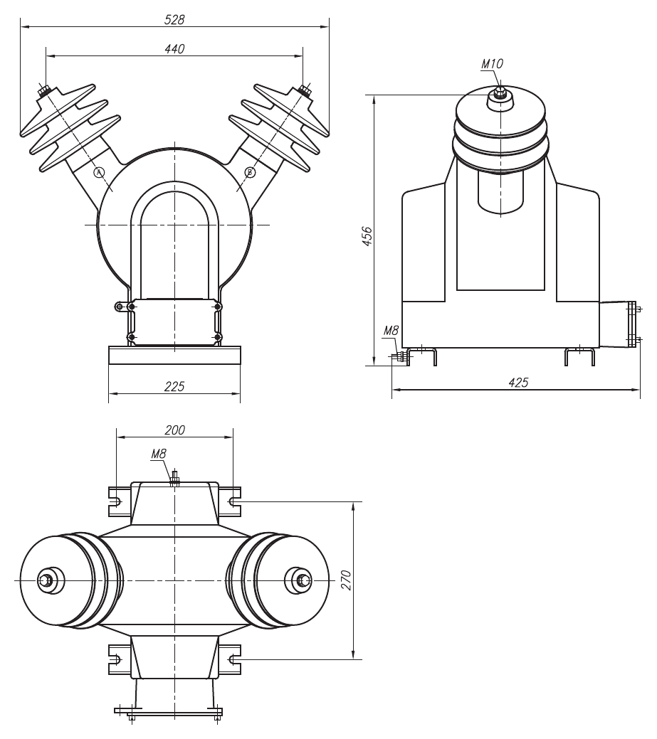
Power supply transformers
DTES-3.3, DTES-4, DTES-5
| TECHNICAL DATA | DTES-3.3 | DTES-4 | DTES-5 |
|---|---|---|---|
| Highest voltage for equipment (kV) | 12 | 12 | 12 |
| Rated primary voltage (kV) | 10 | 10 | 10 |
| Rated secondary voltage (V) | 242 | 242 | 242 |
| Power-frequency test voltage 50 Hz, 1 min. (kV) | 28 | 28 | 28 |
| Impulse voltage 1.2/50 µs (kV) | 75 | 75 | 75 |
| Rated frequency (Hz) | 50 | 50 | 50 |
| Rated power (kVA) | 3.3 | 4 | 5 |
| Valid standards | EN/IEC 60076-11 | ||
| Mass (kg) | 65 | 71 | 78 |
| Mounting position | Horizontal and vertical, outdoor mounting | ||
| Operating temperature range | -55°C to +75°C | ||
At the customer's request, we can also produce other combinations of rated transformation ratios.
When ordering, be sure to state the primary and secondary voltages and power.
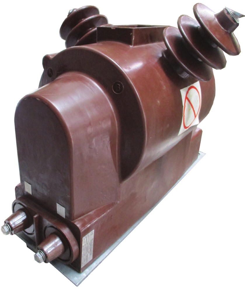
Power supply transformers
DTES-10, DTES-17, DTES-21
| TECHNICAL DATA | DTES-10 | DTES-17 | DTES-21 |
|---|---|---|---|
| Highest voltage for equipment (kV) | 12 | 12 | 12 |
| Rated primary voltage (kV) | 10 | 10 | 10 |
| Rated secondary voltage (V) | 242 | 242 | 242 |
| Power-frequency withstand voltage 50 Hz, 1 min. (kV) | 28 | 28 | 28 |
| Impulse voltage 1.2/50 µs (kV) | 75 | 75 | 75 |
| Rated frequency (Hz) | 50 | 50 | 50 |
| Rated power (kVA) | 10 | 17 | 21 |
| Valid standards | EN/IEC 60076-11 | ||
| Mass (kg) | 145 | 165 | 185 |
| Mounting position | Horizontal and vertical, outdoor mounting | ||
| Operating temperature range | -30°C to +45°C | ||
At the customer's request, we can also produce other combinations of rated transformation ratios.
When ordering, be sure to state the primary and secondary voltages and power.